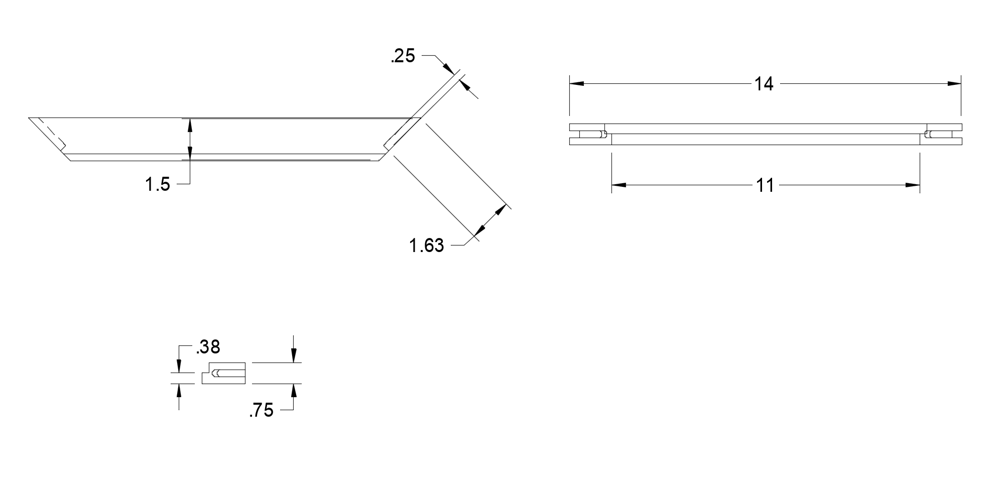
I have seen many designs for tensegrity tables on the web. I decided to make one of my own design. The morning was spent designing the wood frame for the top and bottom in Fusion 360. The plan for one of the eight identical frame members below is the fruit of this labor. The table top and bottom frames will be held together with walnut splines inserted into the 1/4" deep dadoes.
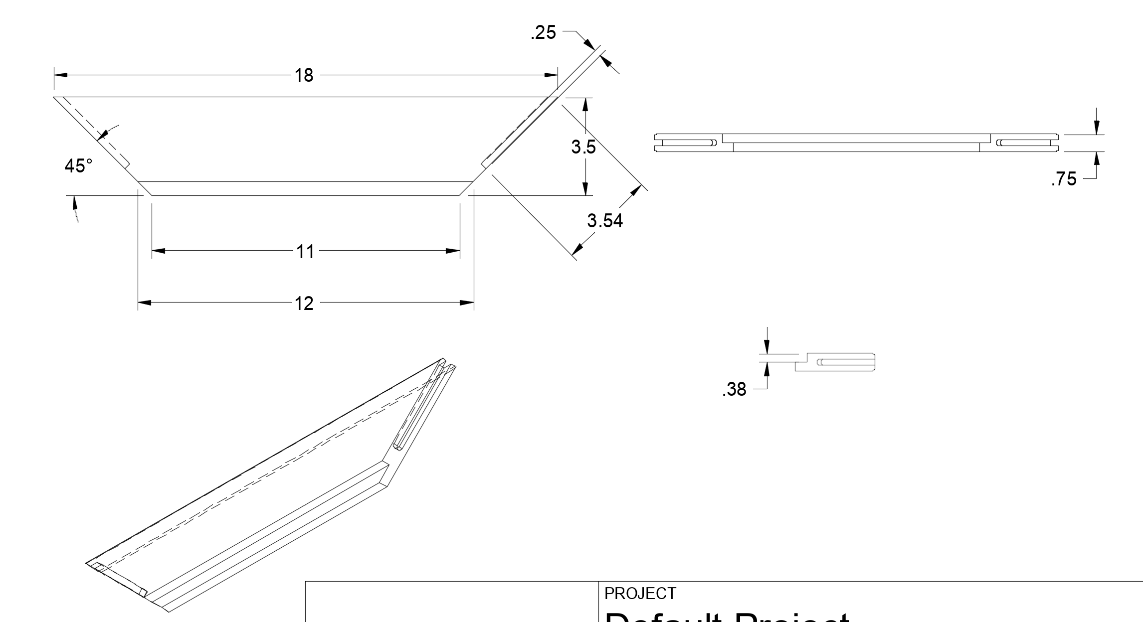
The frame will be made from maple, if I can find sufficiently straight boards at Menards. There will be four connectors sitting between the top and bottom frames. These will be made from walnut for contrast. A 3/8" tempered glass square will be inserted in the top. The top frame members won't be cut until the glass has arrived and been measured. Stainless steel 20 ga. (0.032") wire will be used to provide the opposing tension.
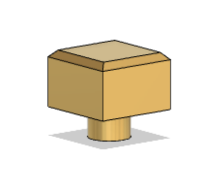
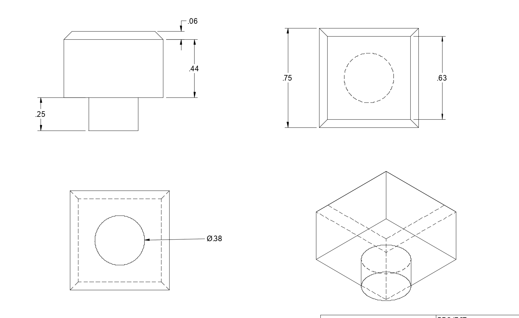
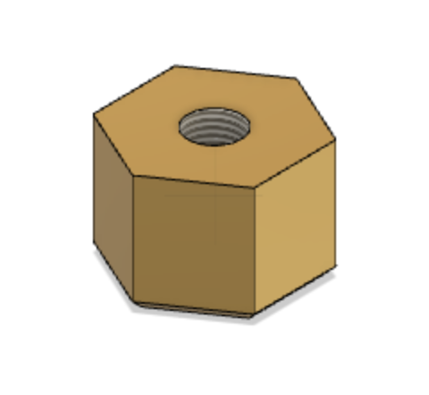
I have given some thought to the devices that will hold and tension the wire. The top holders will use square brass blocks with cylindrical extensions. The wire will be inserted in the extension and the block will be inserted into the table top in a mating square hole. I will leave the top protruding for aesthetic appeal. A hint of G&G maybe.
The wire holder will have a hole cross-drilled through the cylindrical extension. I was unable to figure how to draw a sketch on a round surface, so did not include the cross-hole for the wire. [Even though I have done it before!]
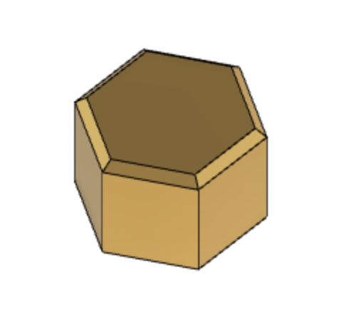
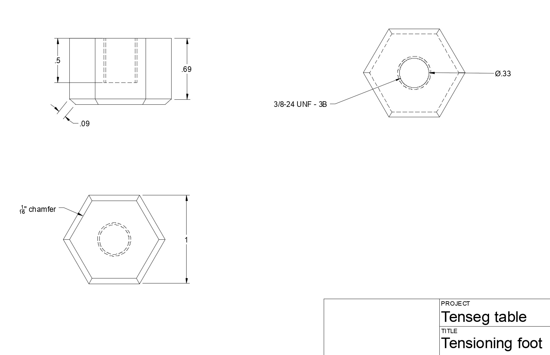
The bottom wire tensioners will provide the tensioning and serve as feet. The bottom frame will be drilled to house short threaded rods. The rod will be cross-drilled for the wire. The feet will have a threaded mating hole. Turning the feet clockwise will draw the wire taut. The feet will also be made of brass, but their design is still undecided, though a tentative plan is shown below.
What I am calling the connectors will descend from the top and rise from the bottom frames: two each. Their length should be 2/3 to 3/4 the desired distance between frames. That leaves 1/3 to 1/2 of the distance, respectively, between the connectors for the tensioning wires. They need to be at an angle relative to the frames such that their ends are directly above and below each other. They will be held to the frames with a mortise and tenon joint. (Maybe a pinned mortise and tenon.) It is not yet clear how best to affix the wires between the connectors. Potentially a variant of the foot so there is control over the wire length.
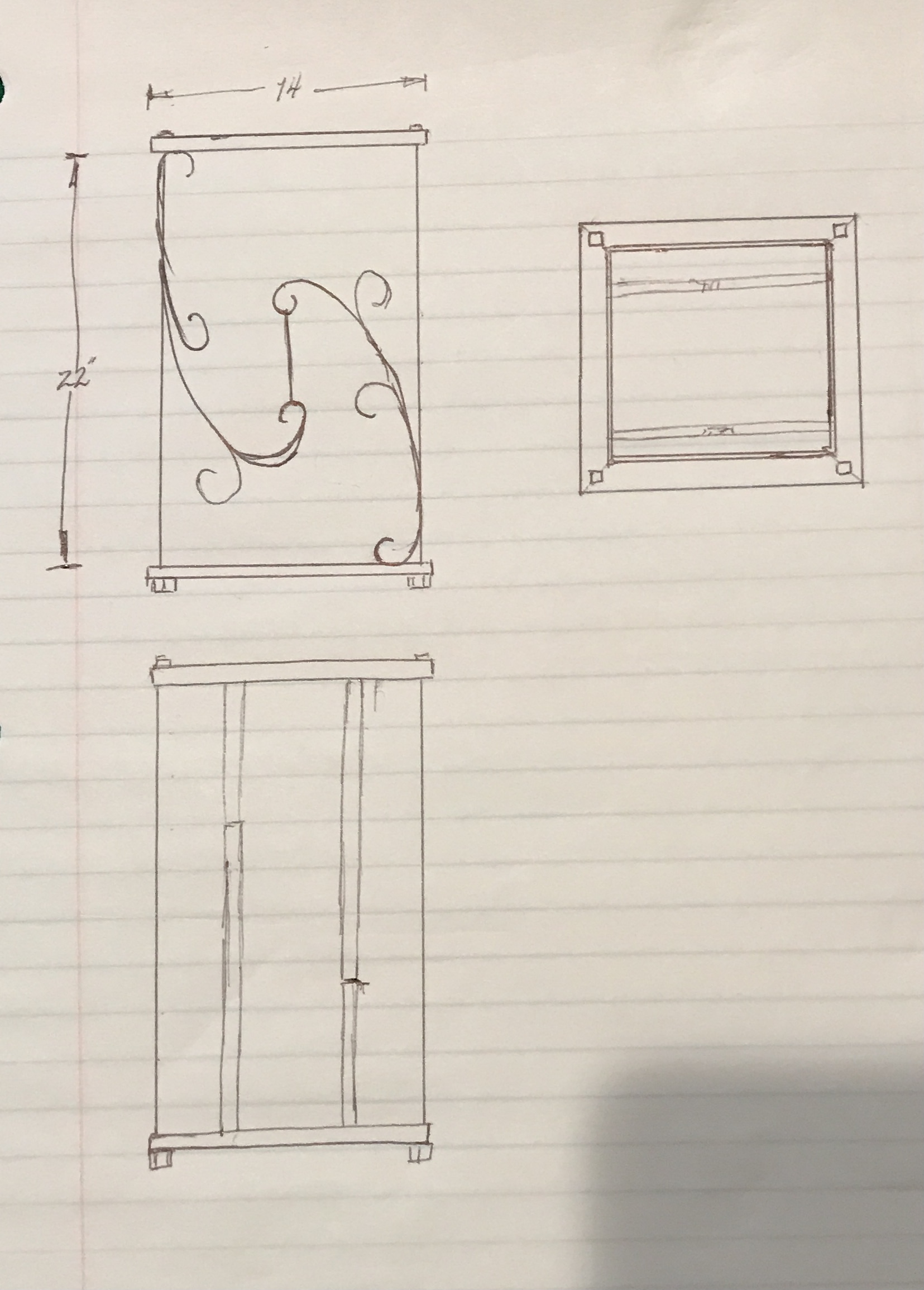
After sleeping on the design I realized that the table as planned will be essentially cubic. It is also very large at almost 20". The G&G side table is 22" tall and the top is 14" square. Going to a smaller top means the frame can be narrower and will look less massive. A smaller top at the same height seems much more appealing. The ratio of top dimension to height is 1.57 or close to the golden ratio.
Back to Fusion 360 and spent two hours trying to figure out how to make different dimensions depend upon one another. The outside of the table top frame member was set to 14", and labeled Frame. The Width was set to 1". A second line was drawn parallel to the first outer frame line, Width inches away. The length of this line was set to Frame - 2 * Width. Lines were drawn from the ends of the Frame line to the ends of the inside line at 45°. The lengths of these lines were defined as sqrt(2*(Width/1in)*(Width/1in)). As it turns out sqrt (and pow()) require dimensionless quantities, thus the division by 1in in both occurrences of Width! Searching the Autodesk content was useless, but searching the Forum quickly pulled up the relevant information.
Coincident constraints are used to make a line end at a point.
A rough sketch was made of the table and supporting connectors. Just from inspection there is a worry that the corners of the table are not sufficiently supported. A mockup needs to be made to find the best way to utilize connectors to maximize stability.
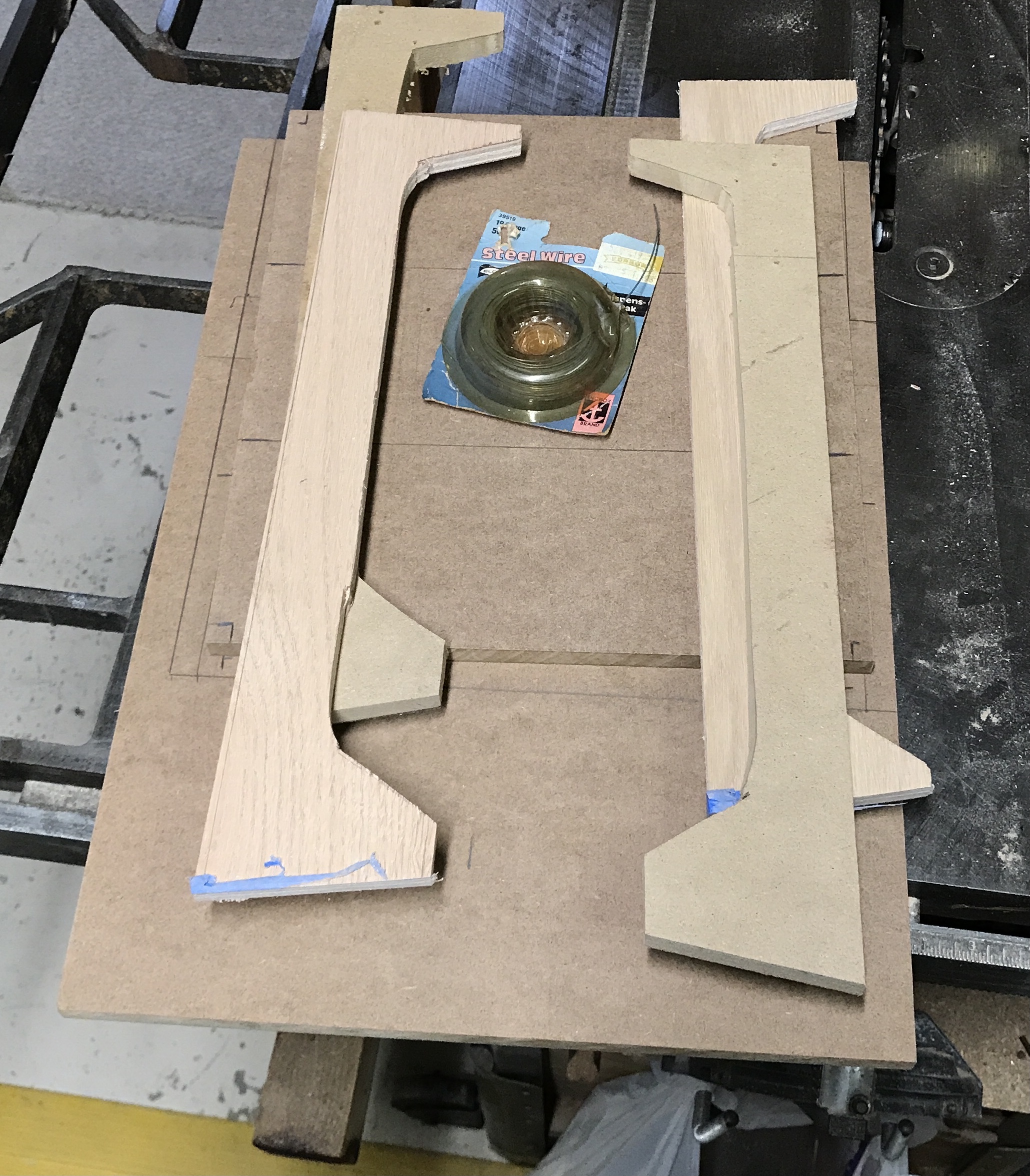
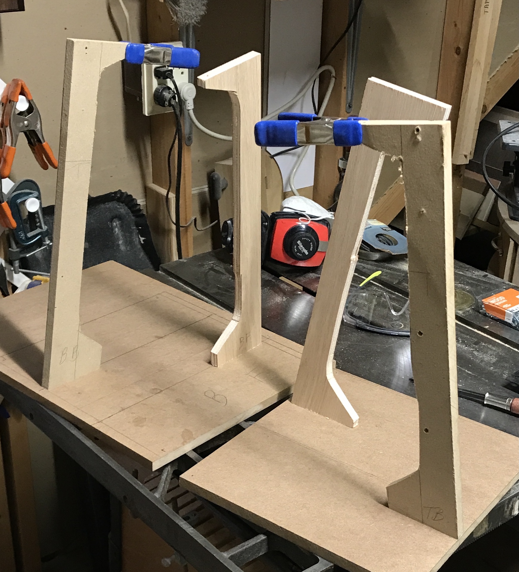
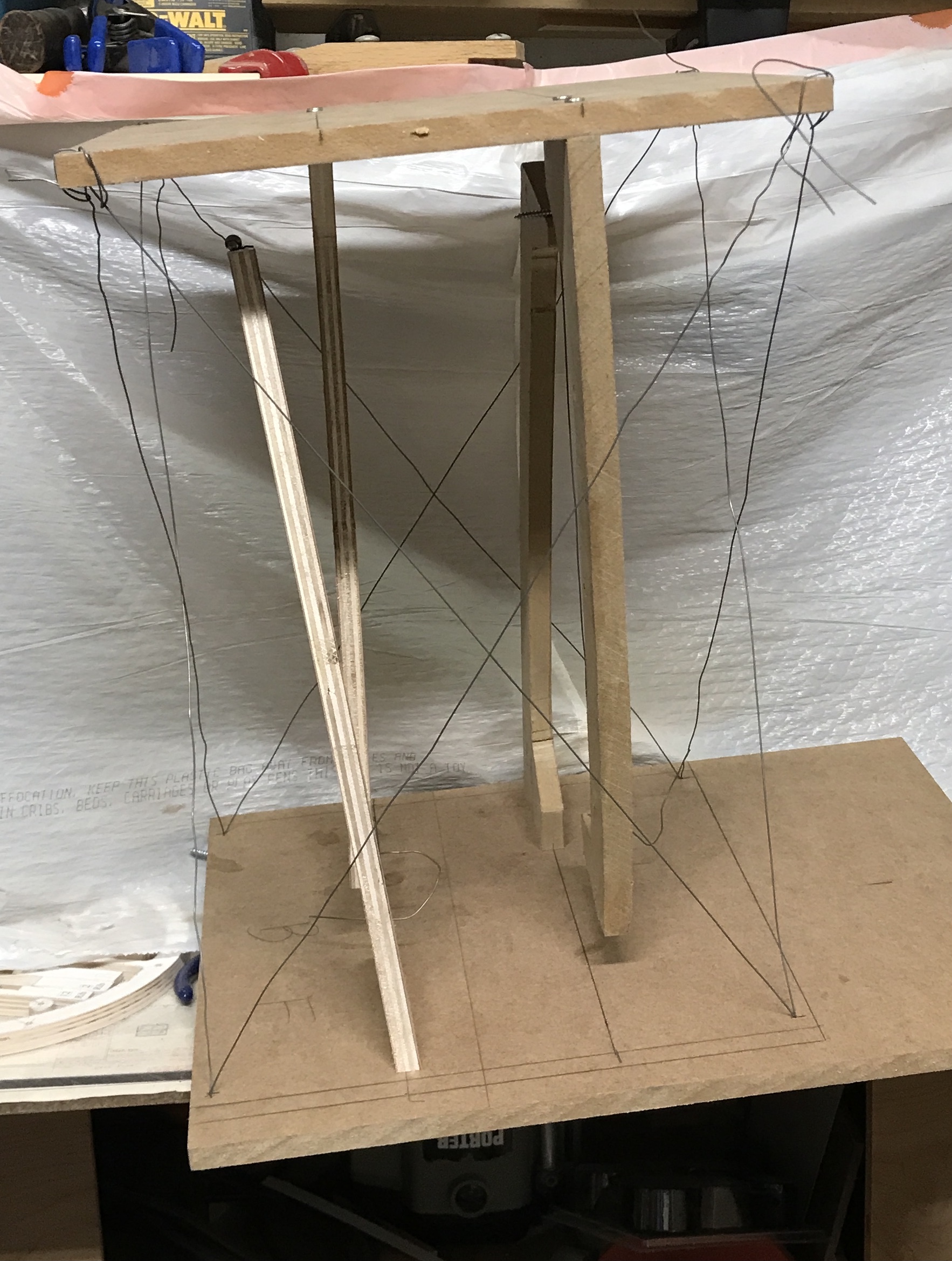
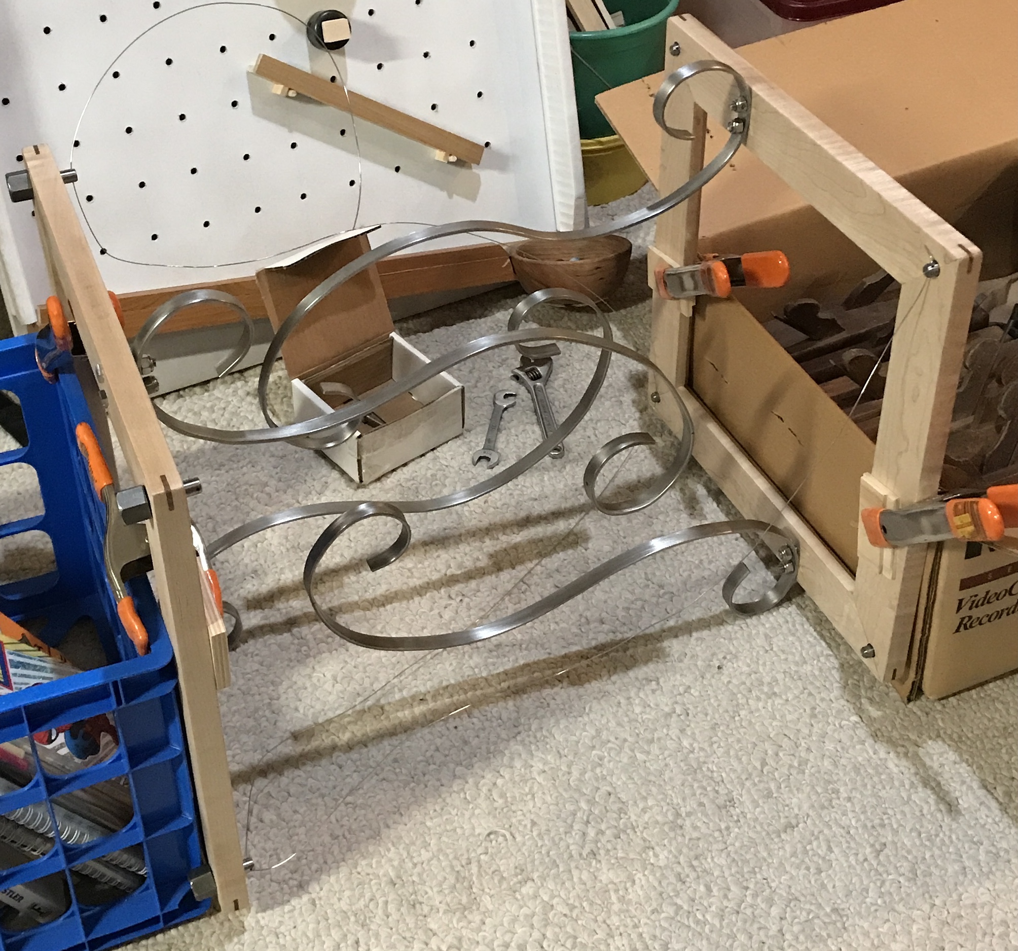
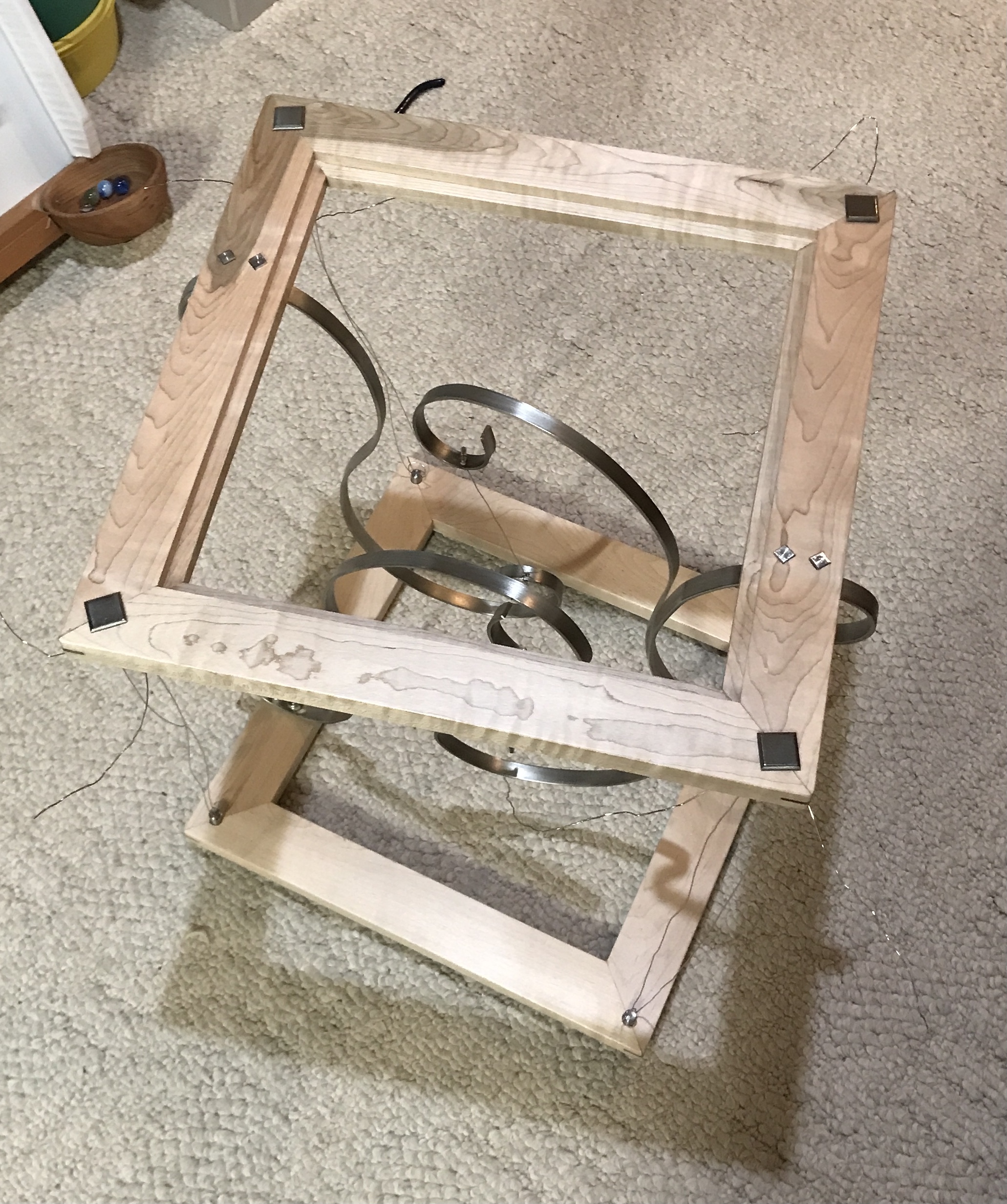
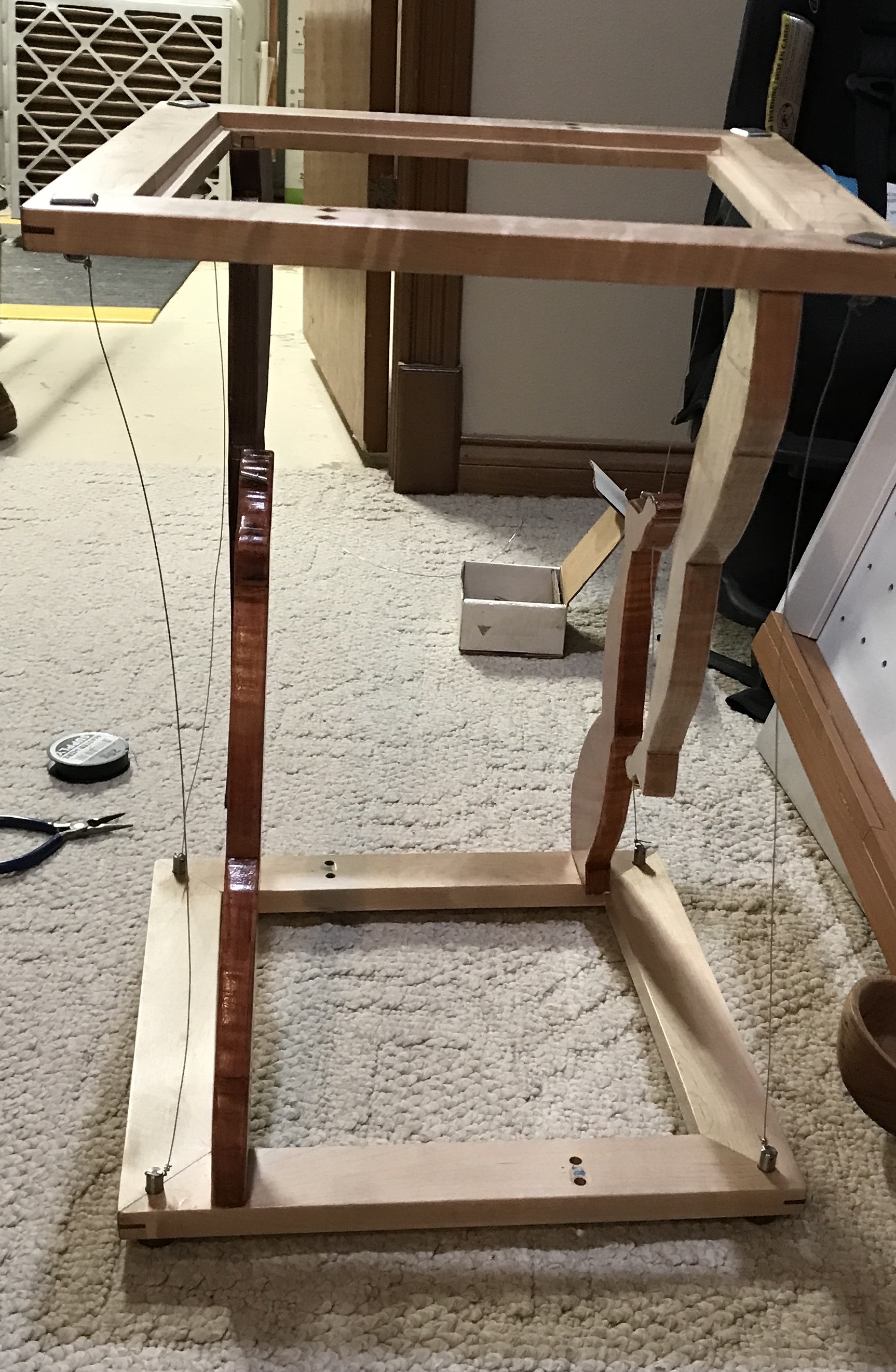
A prototype was constructed this afternoon. It has a 12" square top and is about 20" high. Some galvanized wire was found in the garage. The connectors were cut out of 1/2" stock with a jigsaw. The angle was estimated and cut. Some sanding was needed to flatten this cut end. Holes were drilled in the top and bottom corners (3/8" in from the corners) for the wires. The connector locations were laid out on lines 4" from the ends so they evenly spanned the 12" top. Through holes were drilled for #8 screws and these were transferred to the connector ends. The ends were drilled and the connectors were screwed to the top and bottom with two screws each. Wire holes were also drilled in the free ends of the connectors. The particle board split on one connector, which is why the photos show the two clamps. The first photo below shows the prototype parts. The second shows the connectors screwed to the top and bottom.
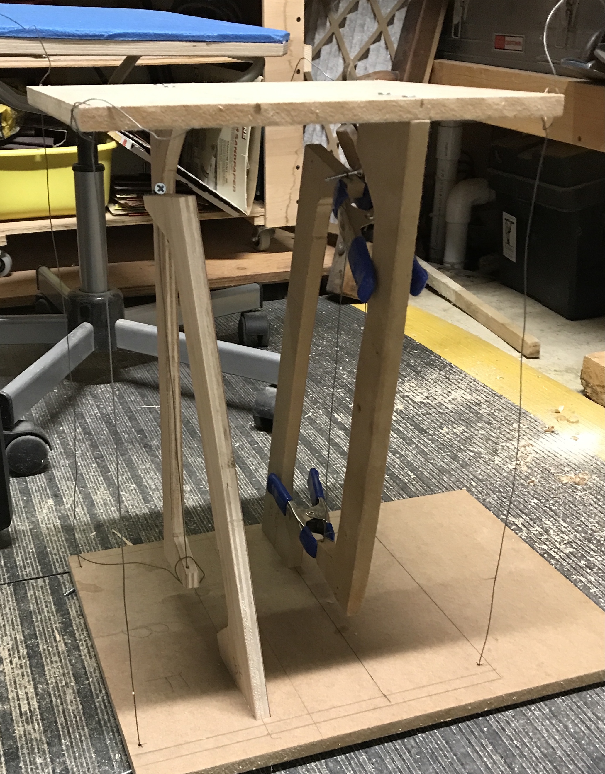
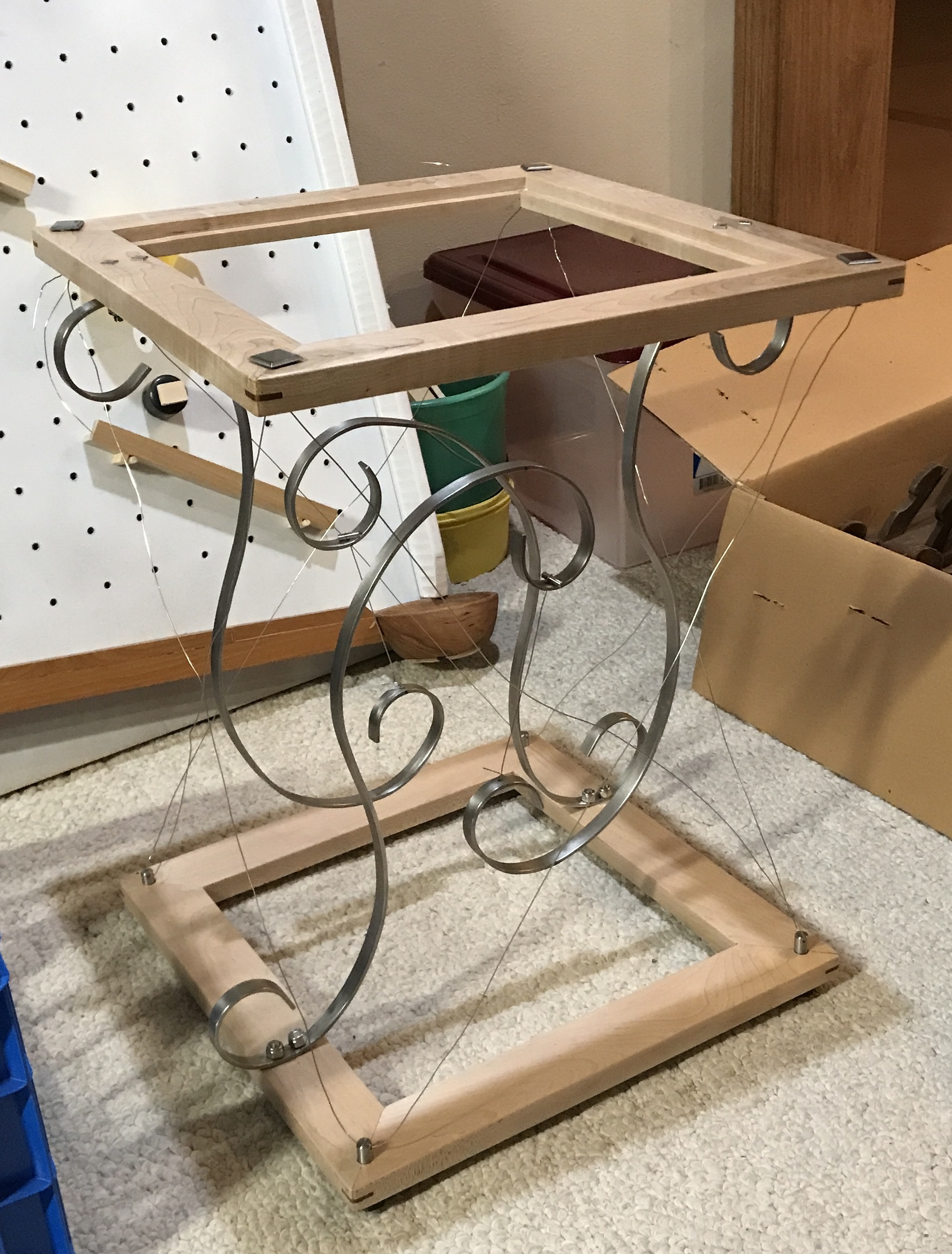
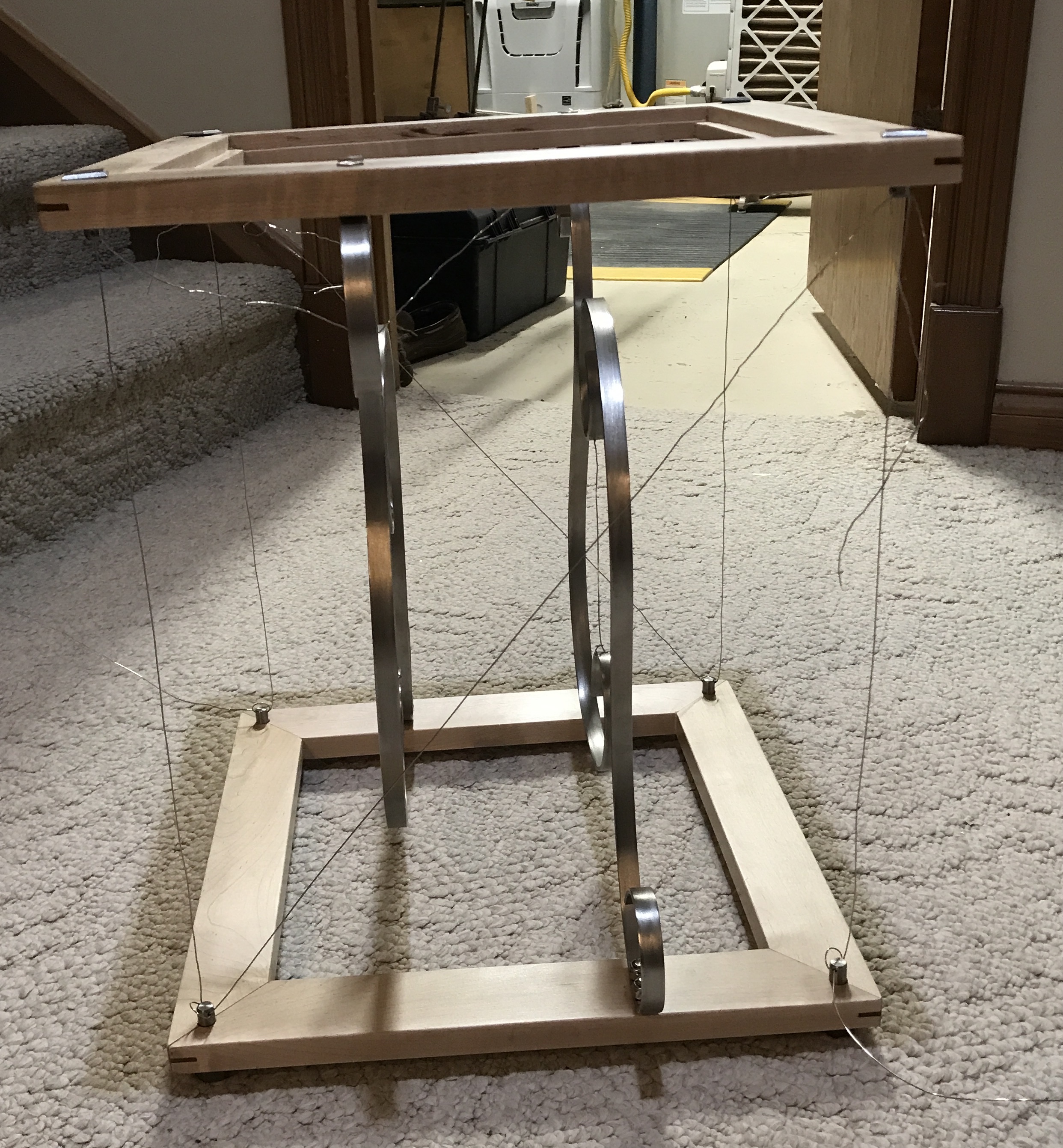
Four 26" lengths of wire were measured out and cut off. Two 16" lengths were also cut. Each long wire was wrapped around a screw on one end. The other end was threaded through a corner hole in the bottom and its mating corner hole in the top. The wire was simply wrapped around the corner. The wires for the connectors were treated the same way. The wires were tightened one after the other until the table was able to stand. One corner was quite low and this was fixed by tightening the catty-corner wire. The table wiggles but is remarkably sturdy up and down. The photos show it assembled. It is time to proceed with the design of the real thing. I am considering bent metal connectors.
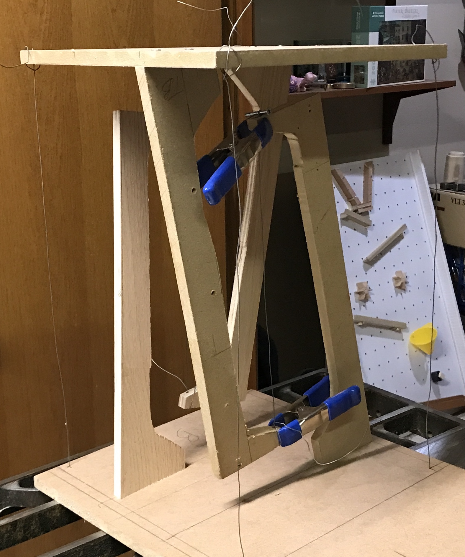
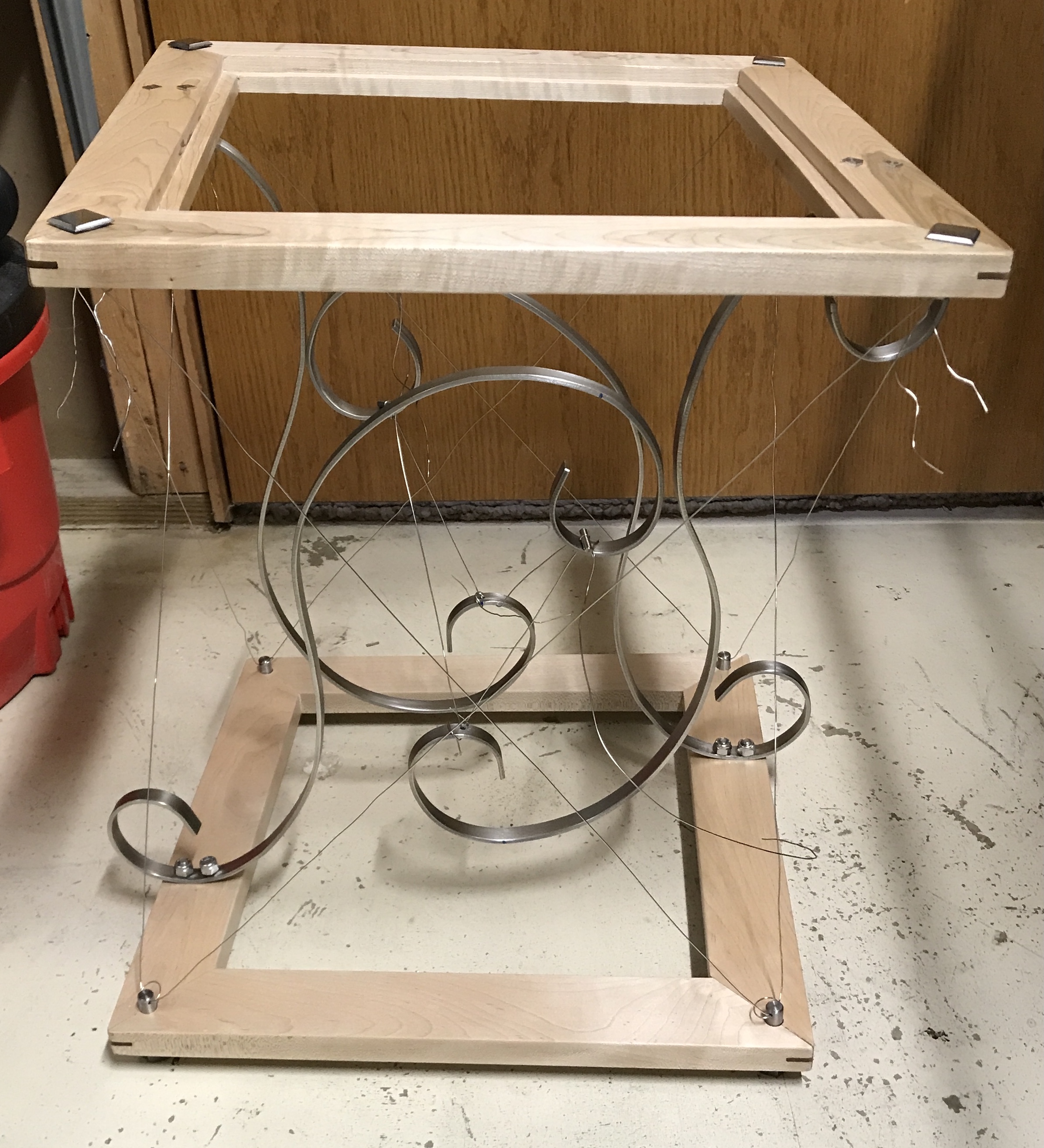
The stainless steel bars for the connectors and the stainless steel wire arrived. The glass needs to arrive and be measured before starting the frame. The prototype had one issue that bothered me. It is very solid vertically, but wobbles in a twisting direction. An idea occurred on how to fix it. Two wires were used from each bottom corner and proceed not to the corner above, but to the two adjacent corners. This wiring scheme is shown in the following photo. The prototype is even sturdier wired this way with no ability to twist.
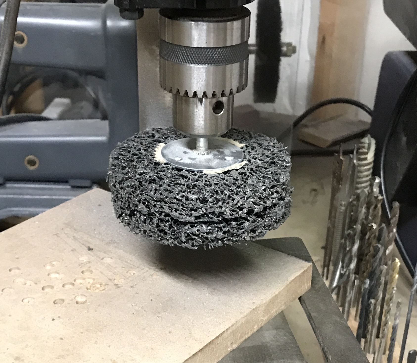
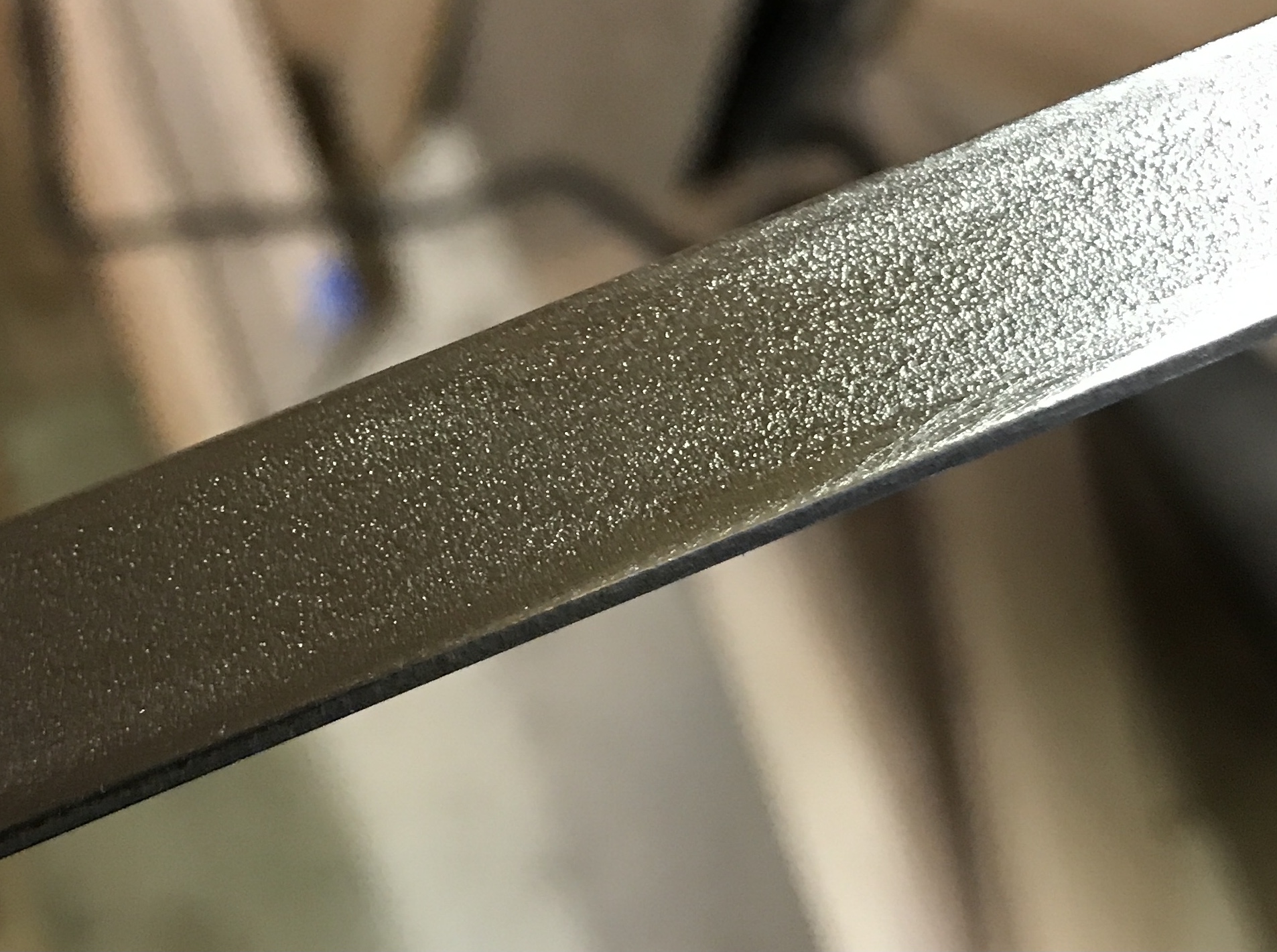
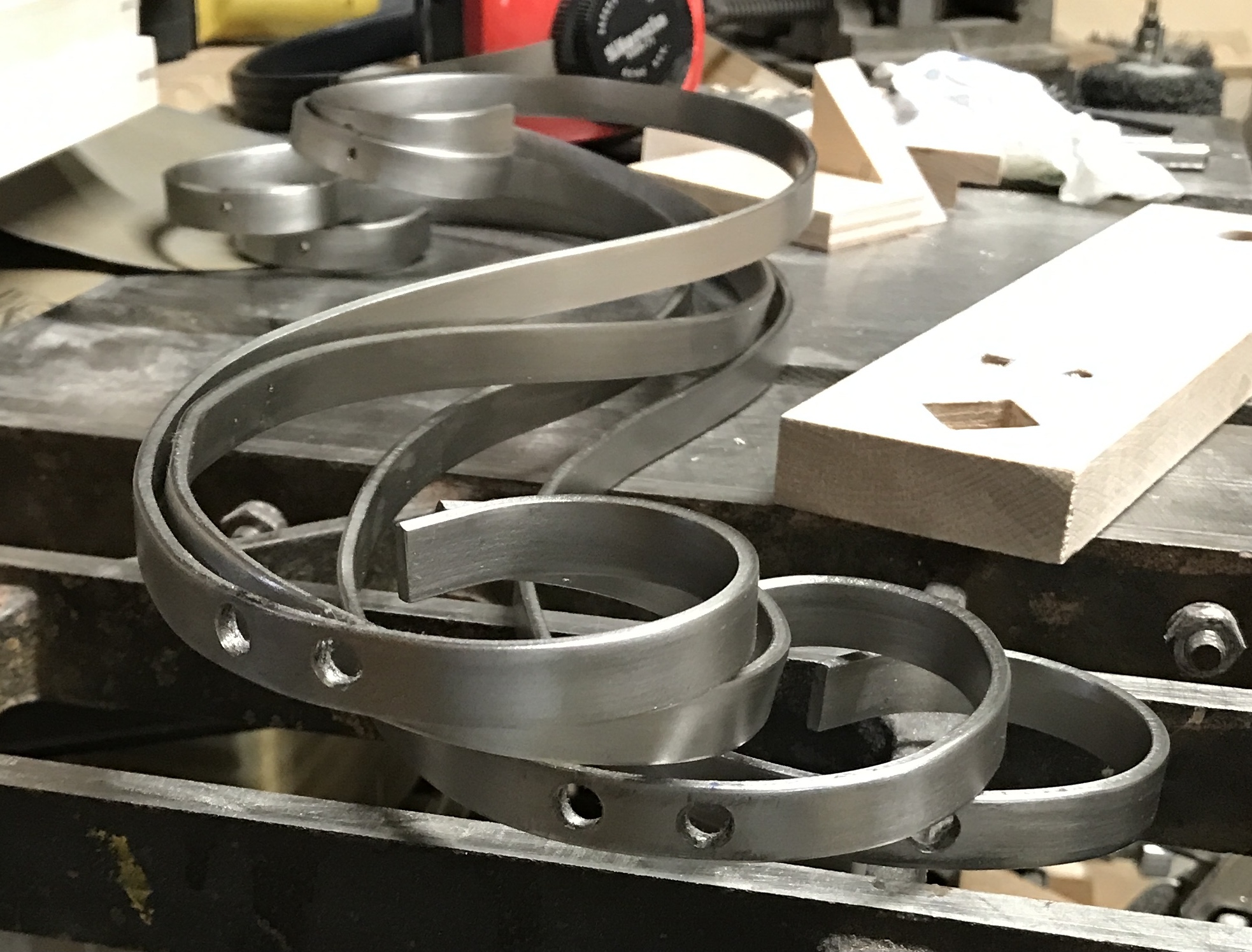
The stainless steel purchased for the connectors was pickled. This is a process in which acid (HCl or H2SO4) is used to remove scale. The surface of the pickled steel has a brown color and is pitted. Both a wire wheel and a 3M deburring wheel were tried to produce a shiny finish. The out-of-round 3M wheel performed best and was used on all four sides of the four 36" long bars. It took about two hours to get the satin finish I liked. The first picture below shows the 3M wheel and the second the finish on the bar.
The glass was supposed to arrive last night. It is now expected today, April Fool's Day, before 8 pm. The glass arrived and is exactly 12.0" X 12.0". Rethinking the dimensions of the frame in Fusion 360 has convinced me to make the frame members wider, 2" instead of 1.5". The increase is necessary to make connector attachment simpler. The drawings above just need the long side of the frame member increased by 2 X 1/2" = 1". Consideration has also been given to reducing the width of the glass holding rabbet. For every 1/8" reduction the long edge needs to be lengthened by 1/4" as the glass is a fixed size. Eight 15" long frame members equates to 10' of wood, minimum.
Wood was purchased after volunteering. Now we are off to the races! Three 1" X 3" X 6' maple boards were purchased at Menards. Only two should be needed. First, the boards will be cut into four 15 1/4" lengths. Second, the width will be reduced from 2 1/2" to 2". Third, the corners will be cut off at 45°. The boards will be labeled as they are cut in an attempt to align the grain around the frame.
The 6' boards were cut to 62" with the circular saw as longer boards could not be cut with the table saw. A "stop" was set using an adjustable fence clamped to the right side of the table saw. The boards were cut with the crosscut sled. The last cut in each board had to be measured as only about 1/2" was left to remove. The boards were labeled as they were cut with labels also pointing to the adjacent frame members.
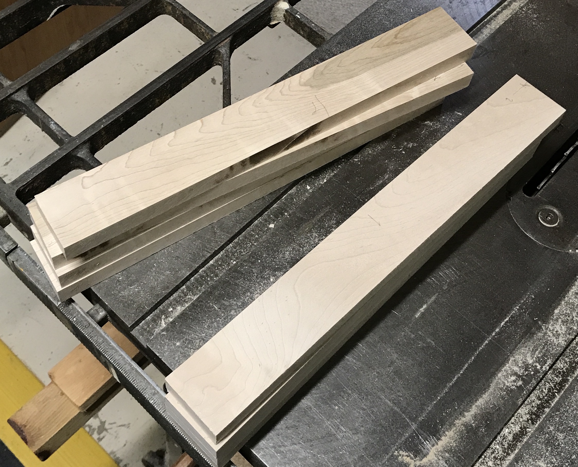
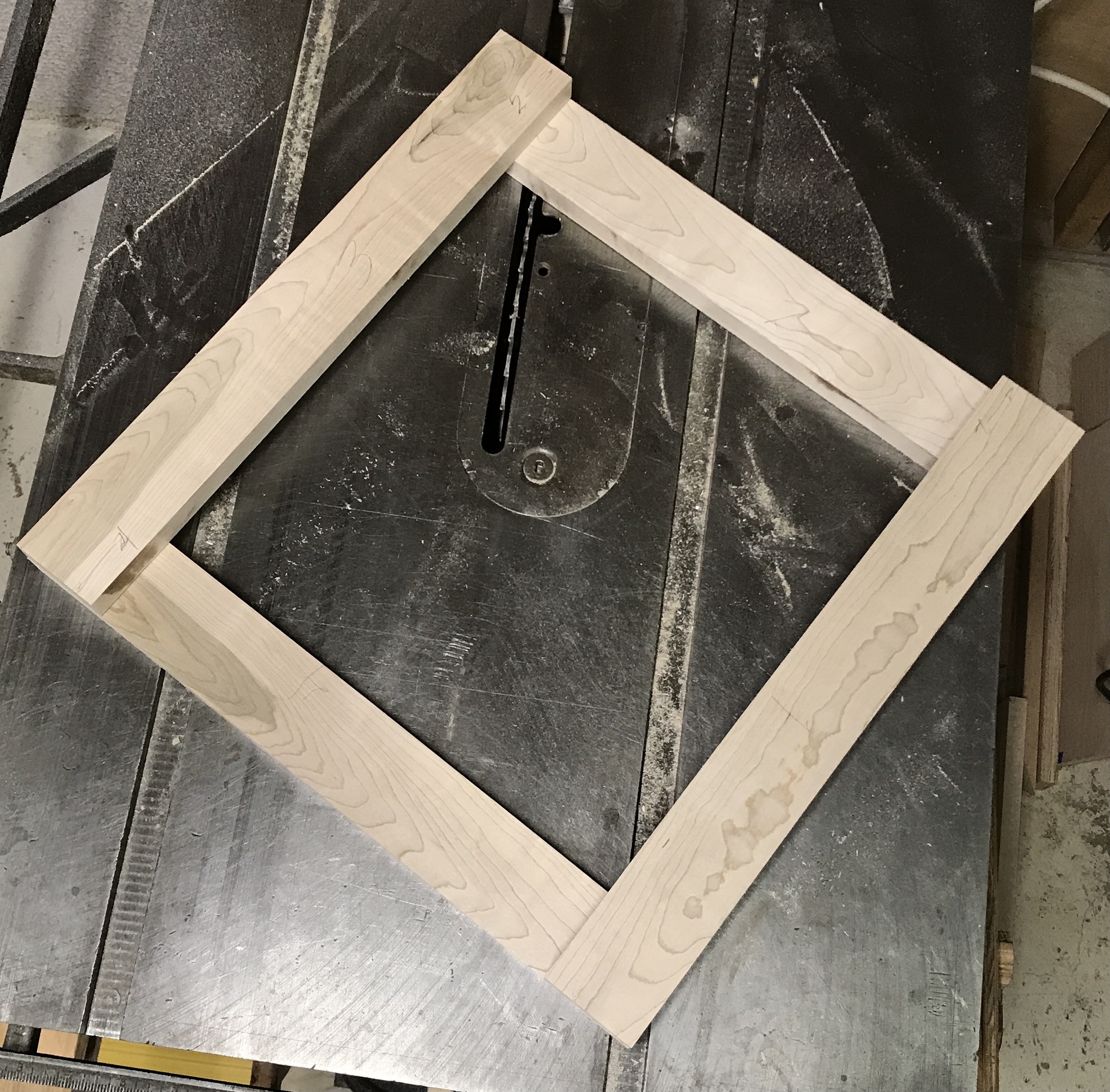
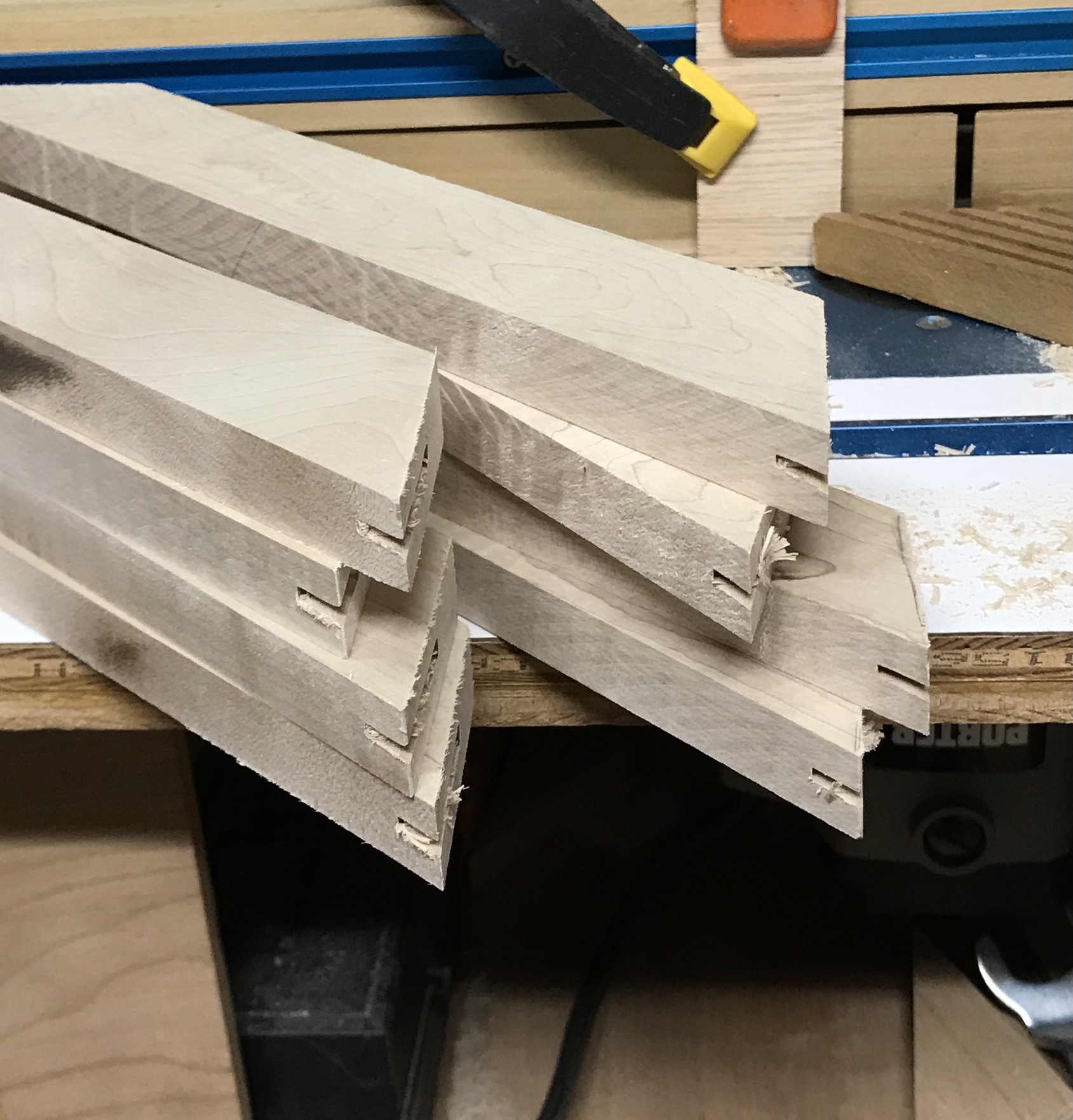
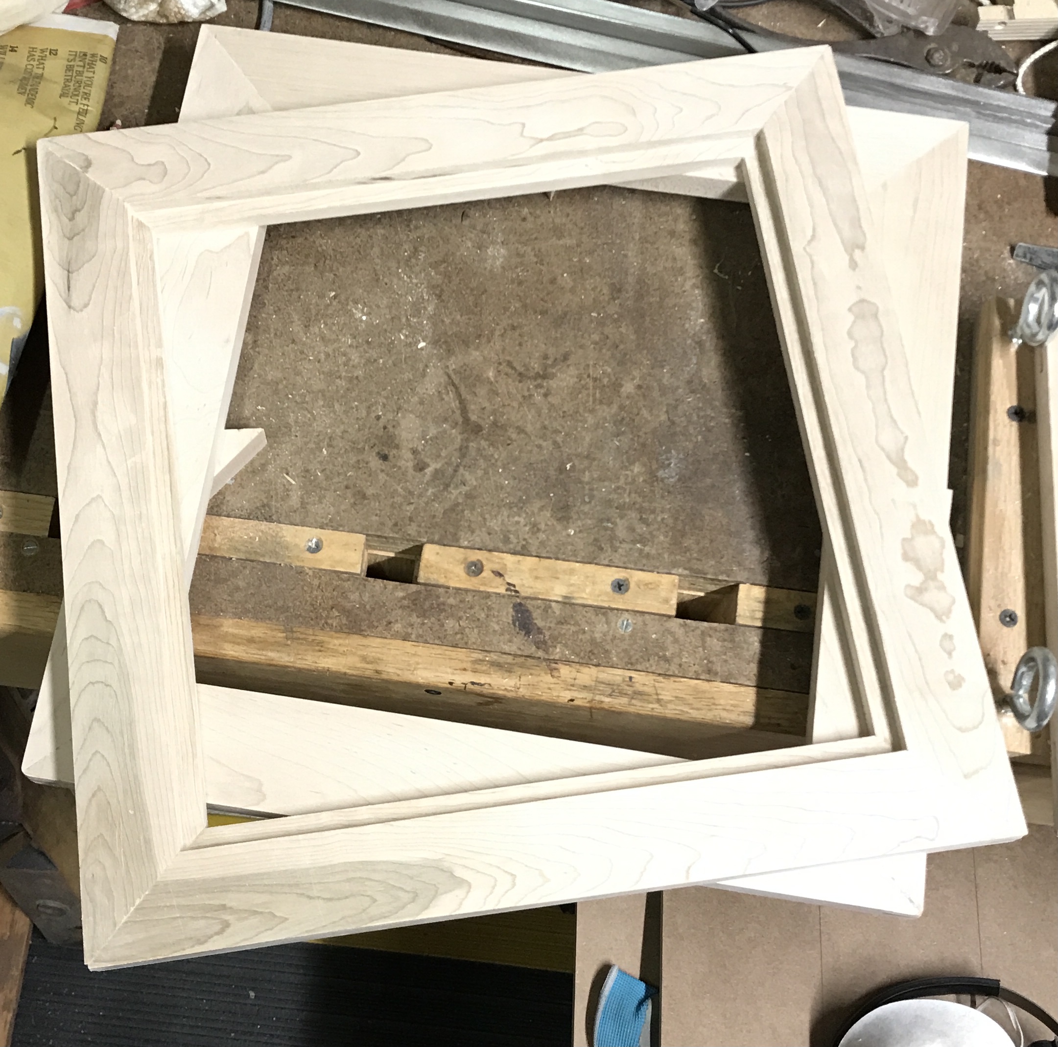
One side of the boards was a little rougher than the other so that side was marked on all eight boards. The fence was put in place and set to 2 1/8" (since the blade is 1/8" thick) from the opposite face of the blade using a square. All eight frame members were ripped to 2". The eight frame members at this stage are shown below.
Both groups of both boards were examined to determine which was best for the top. The chosen set has the better figuring of the two and is shown in the photo below. All sides were marked for the rabbet cut. The dado blade was installed with one cutter and two 0.0065" spacers. It was raised 3/8" and the fence was set at 2". After some experimentation the rabbets were cut on all four frame members.
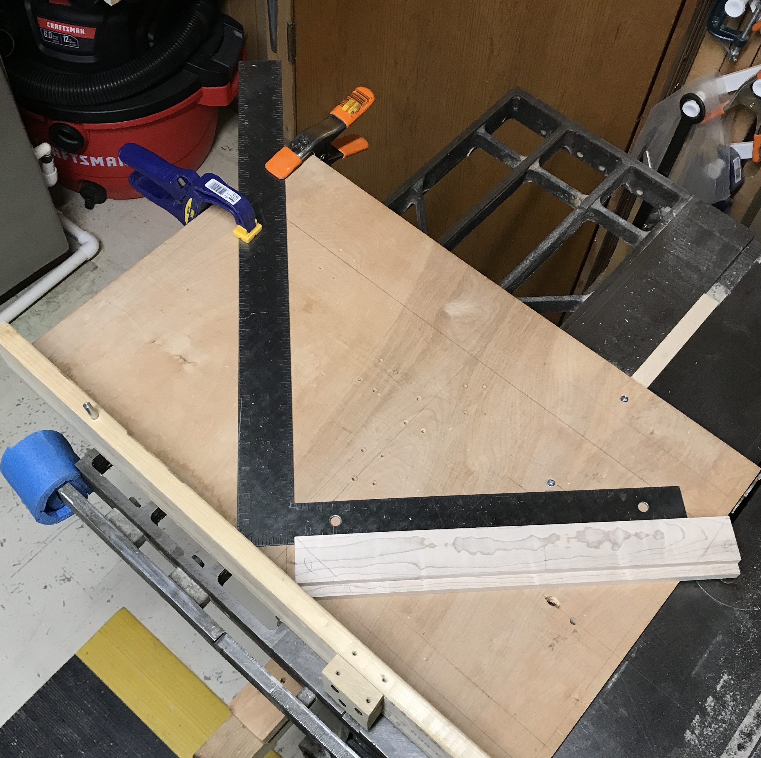
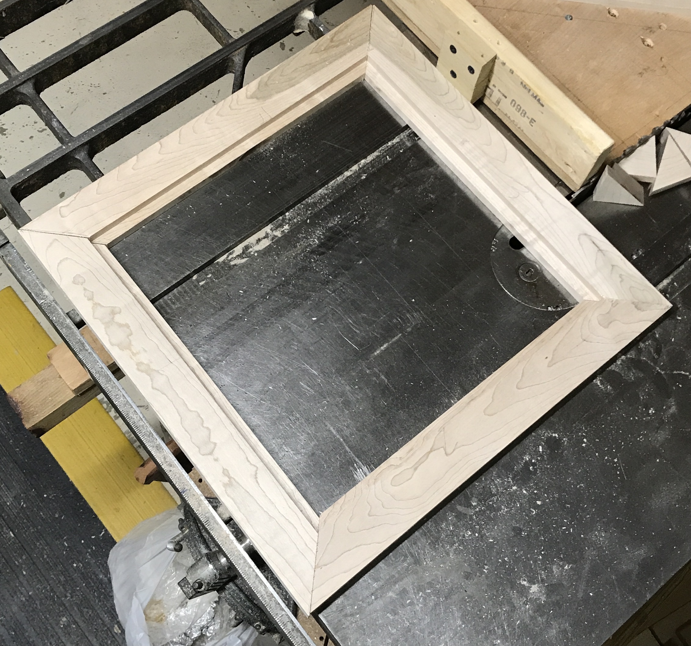
The crosscut sled was used to cut the mitered ends of all eight frame members. A line square to the saw blade edge was drawn across the sled. The framing square was used as a stop. It was set to 45° by assuring both legs measured the same on the drawn line. The square was clamped in place. It was adjusted left-right to set the cut line on the corner of the frame member. The photo shows the setup. The second miter cut on the opposite ends required readjustment of the square farther to the right. It could not go all the way as it stuck out over the cutting edge of the sled, so a spacer was used. The second picture shows the tabletop laid out. The opening is 12" X 12" as desired.
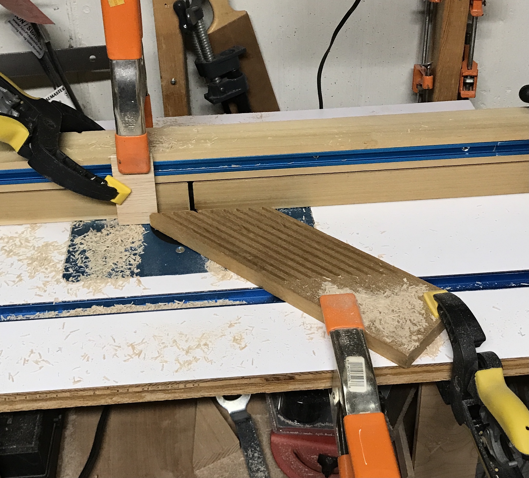
The router table was set up for cutting the dadoes for the splines. The bit was changed for a 1/8" straight bit. The fence was moved to 5/16" from the edge of the bit. A stop was set at 1.5" and a featherboard was clamped to the table. This setup is shown in the first photo below. In order to provide better support for holding the boards on the table at 45° a second frame member was used as backing. After checking and adjusting the setup with a scrap all sixteen cuts were made. All cuts went well. The dadoes had to have the chips dug out. The second picture shows eight of the dadoes.
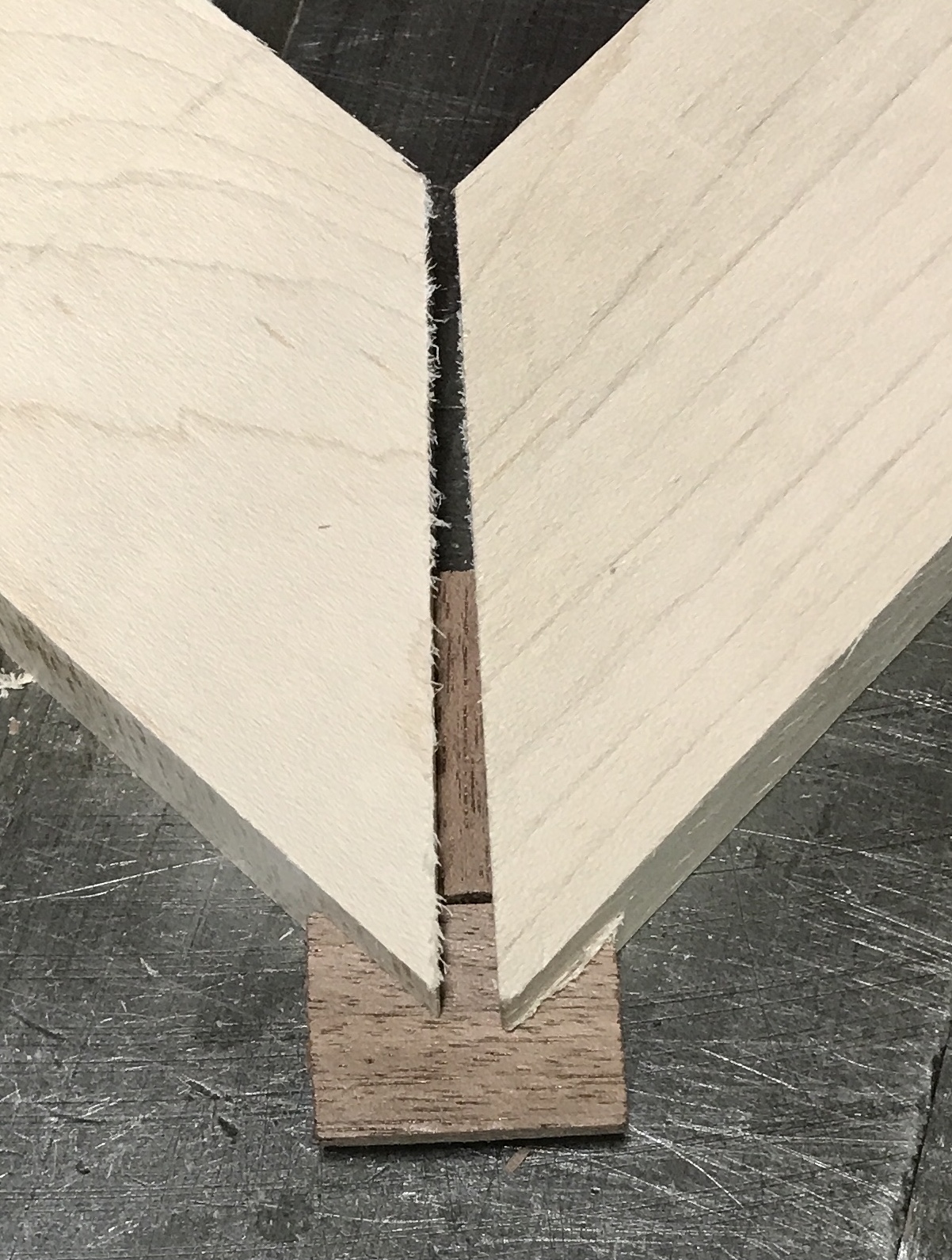
Splines were made for the eight joints. A length of walnut was reduced by 1/8" to 3/4" thick. A 1/8" thick strip was sawn off with the use of the fence on the table saw. This strip was just slightly narrower than the width of the two dadoes in a mated set of frame members. A decision was made to cut two splines for each joint. The first is about 1 1/8" long and will sit in the back of the groove. A second 1" spline will be run crossways through the groove at the front and protruding on both sides. This is the decorative part of the spline and will be cut to fit after glue up. Below is a photo of the joint left open to show the two splines.
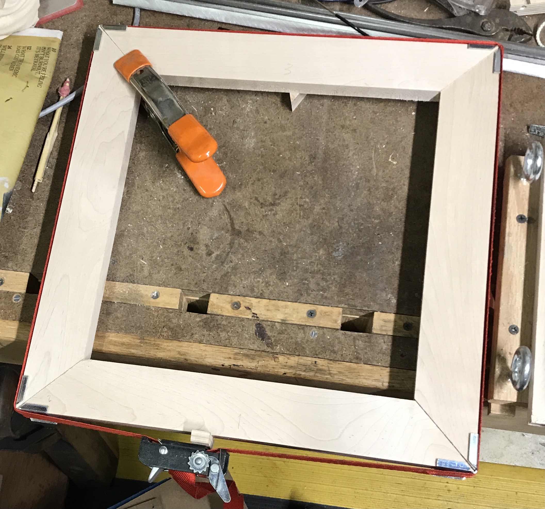
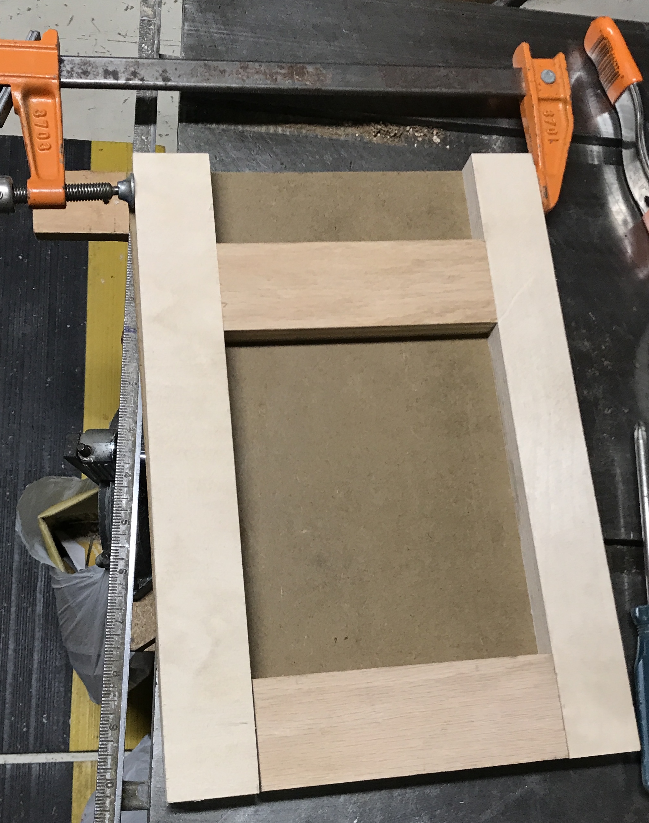
Glue-up was this morning. The four frame members for the bottom were aligned on the table saw surface. Glue was spread on each of the mating faces and put in the dado. The splines were inserted and the corners pressed together. A strap clamp with steel corner fixtures was used to apply the pressure. This process was followed for the top as well. The picture below shows the bottom frame clamped together.
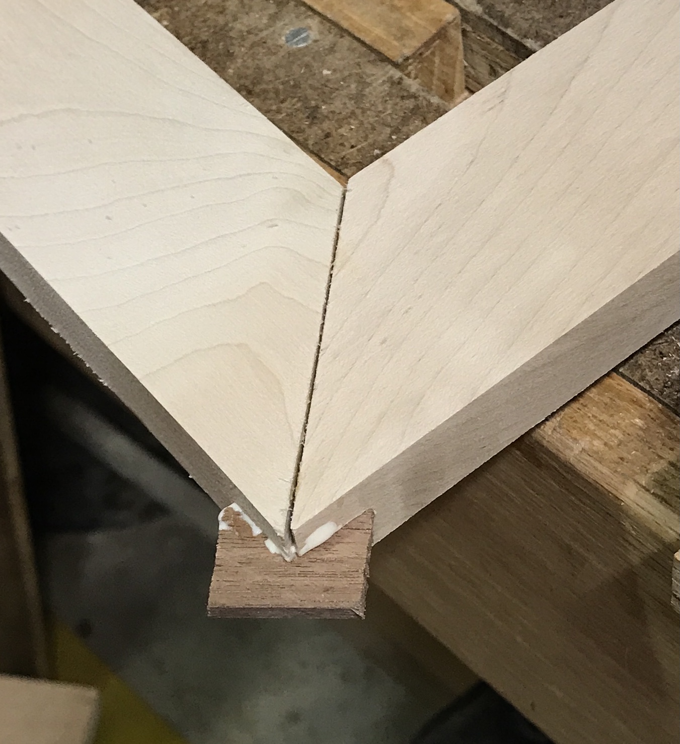
After the glue dried for an hour the strap clamps were removed. Glue was added to the corner dadoes and the decorative splines were put in place. This is seen in the photo below.
The decorative splines were sawn off with the one-sided blade leaving a bit of sanding. All sides of both frames were sanded with 150 grit sand paper using the orbital sander. Glue was used to fill in some of the more noticeable gaps in the joinery. The inside of the rabbet was sanded as well. The only things left unsanded are the corners. I would like them rounded as well as the edges, but do not yet know quite what I want them to look like. The photo shows the rough sanded though quite smooth frames at this point.
Since the supports will be made from steel, I have decided the other fittings will also be made from steel. Cold rolled steel will be used and the fittings will be varnished to inhibit corrosion. Two bolts will be used to fasten the ends of the connectors to the frames. This will require flats areas in the attaching ends. Purchased stainless steel bolts and nuts will be used for these fittings.
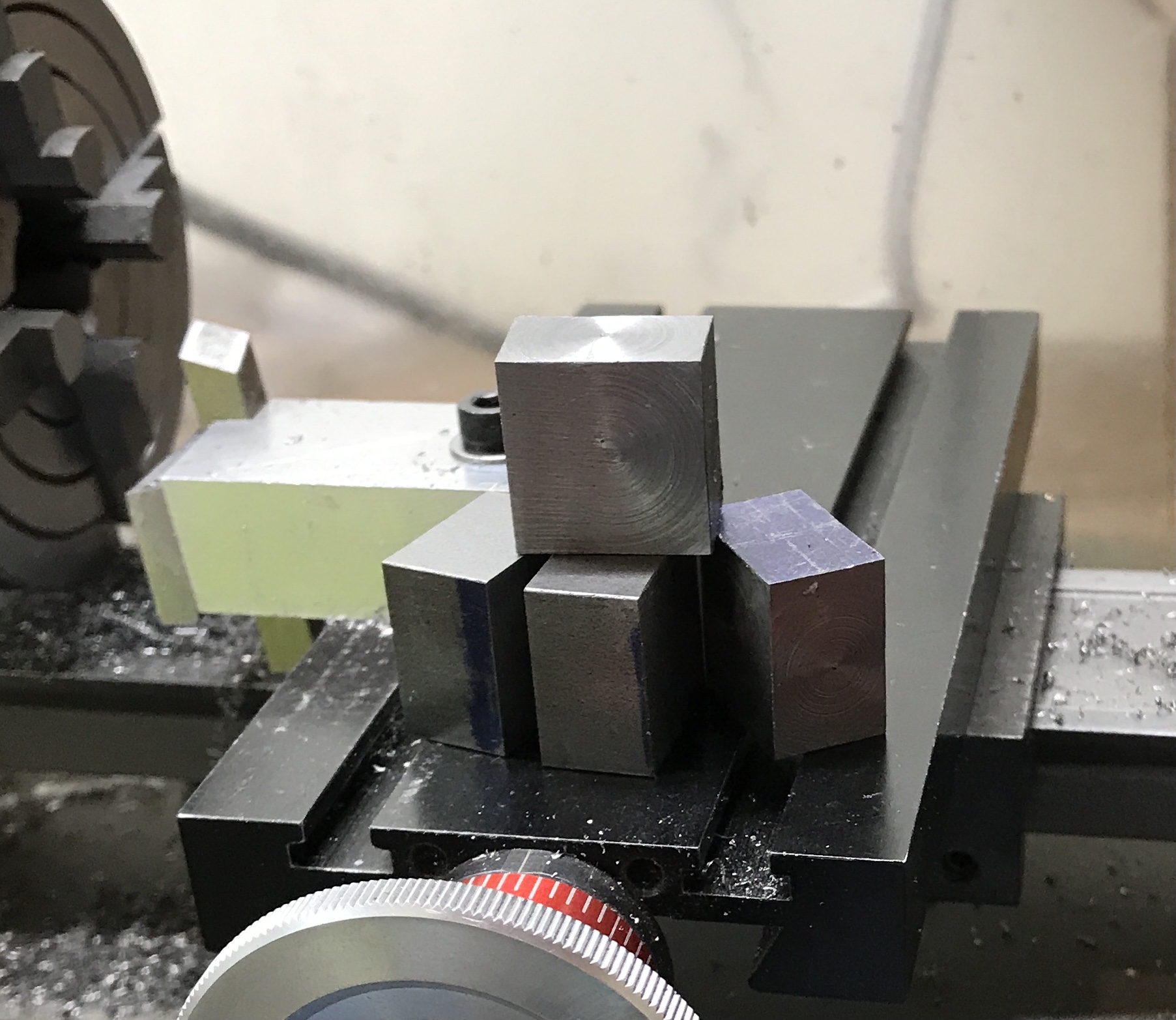
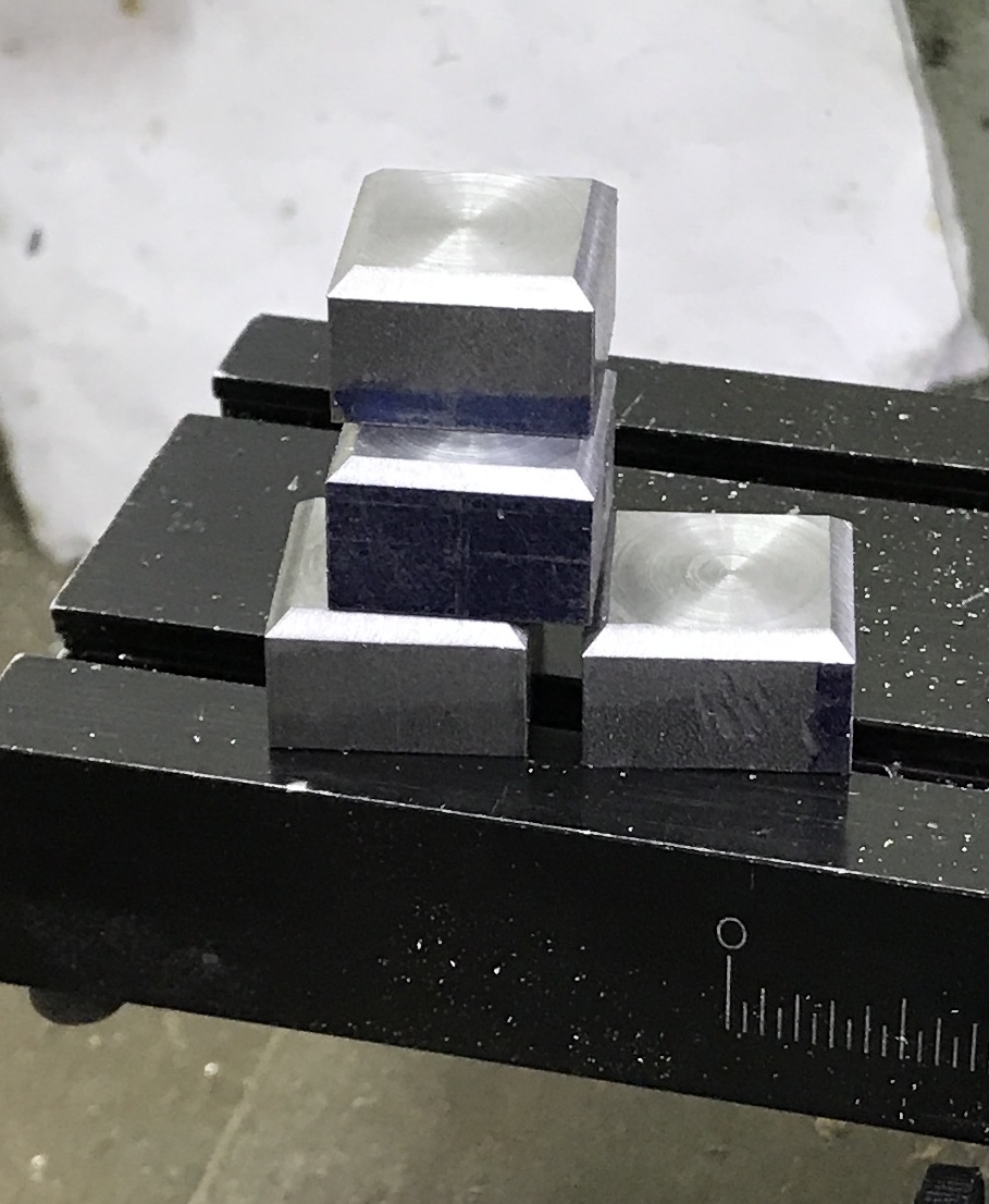
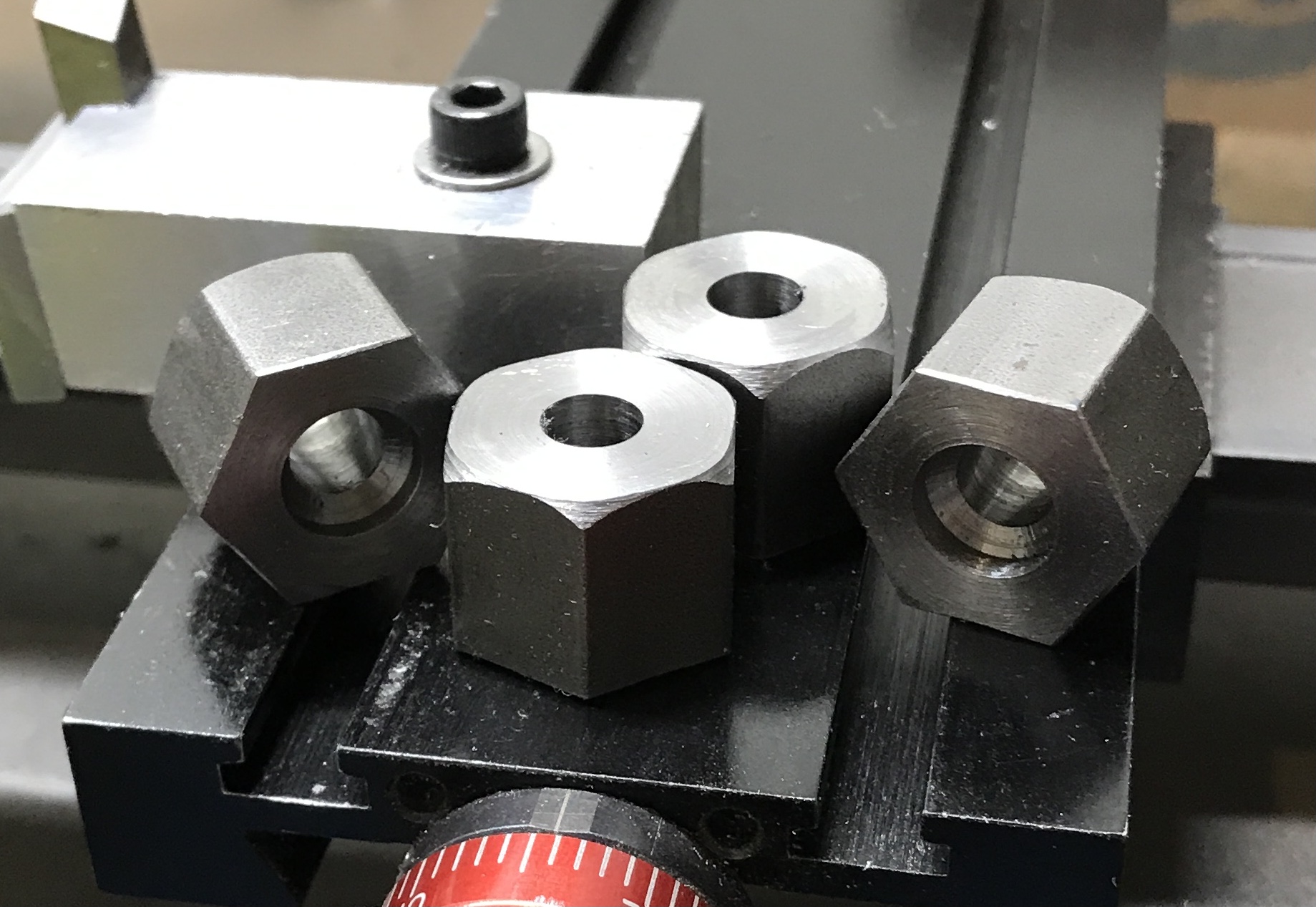
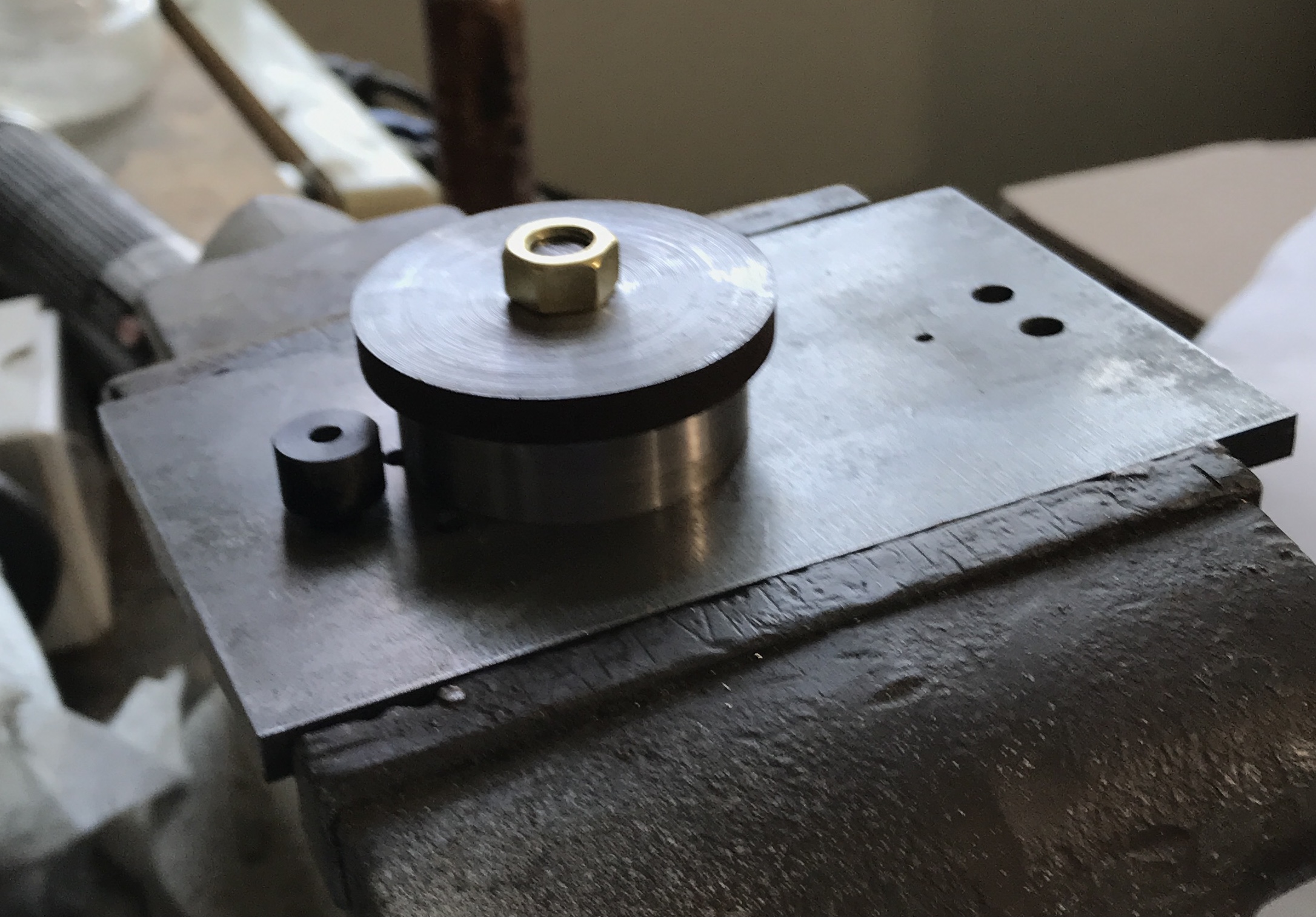
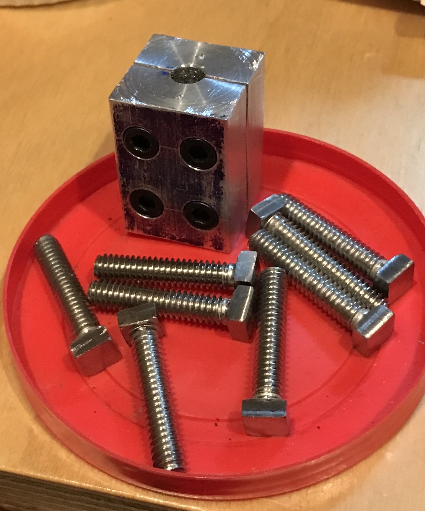
The wire holders for the tabletop were made first. A cutoff of 3/4" steel was found and the scrap from the slotting attachment yoke were used. They were first cut to approximate size with the bandsaw. All faces were cleaned and squared up using the four-jaw chuck in the Sherline lathe. They are about 3/4" X 3/4" X 0.45". The cleanup and the four parts are shown in the two photos below.
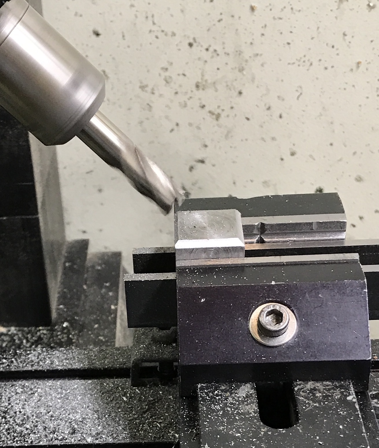
The next step was milling the chamfers. Each part was set on parallels in the vise. The spindle was tilted 45°. The 5/16" four flute end mill was touched off on the part's corner. Cuts were made in passes of 0.010" to a total depth of 0.062". The part was turned and the process was repeated sixteen times. This is documented in the photos below.
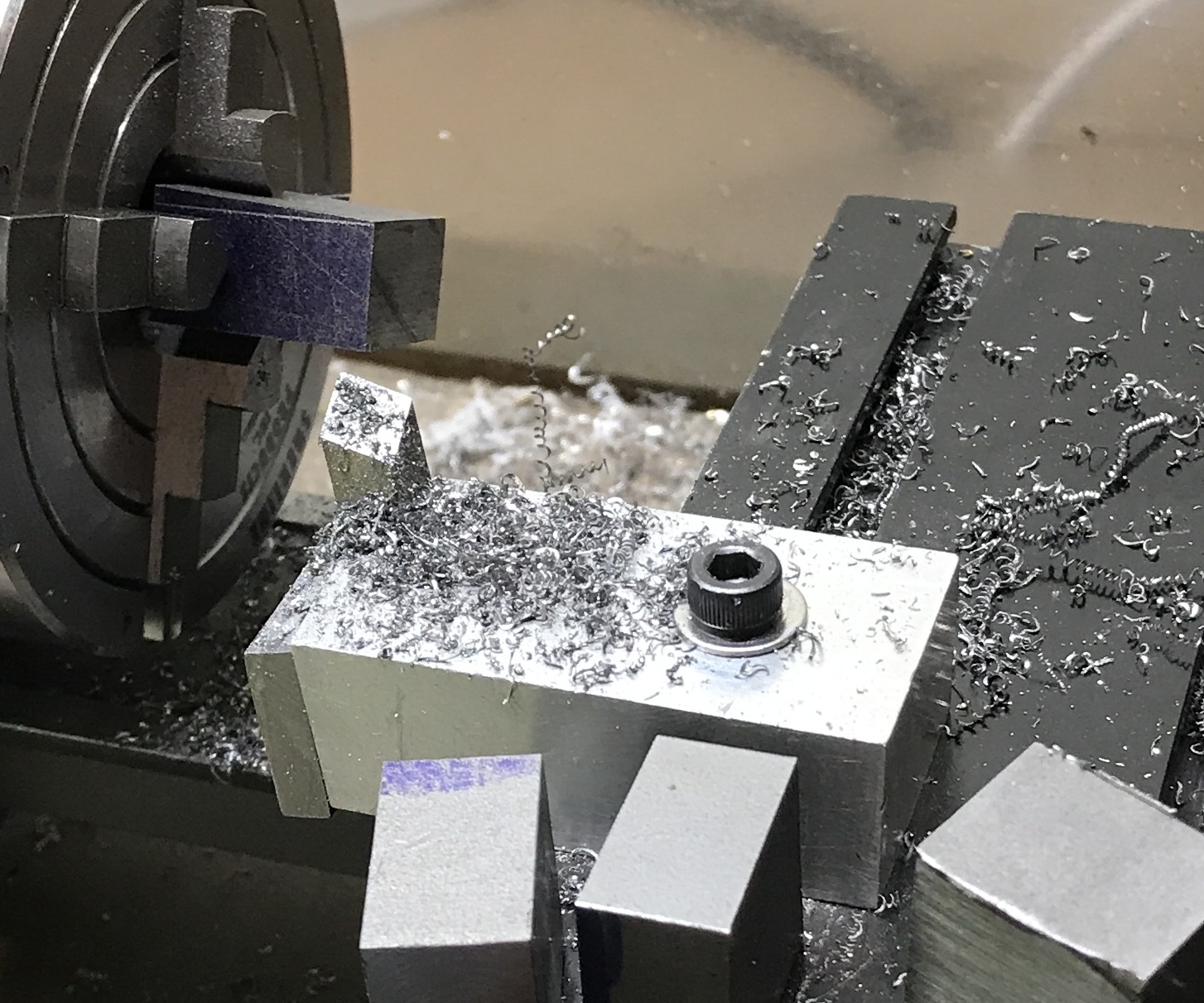
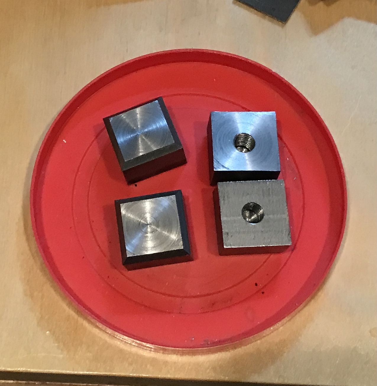
The squares were drilled and tapped for the rod that will hold the wire. The part was again held on parallels in the vise. The center was located and drilling was done with a center drill, a #26 drill, and a #3 drill. This was followed by a 1/4-28 tap. The starter tap only went in about three turns. The tapping was finished with a bottoming tap in the wood shop vise. The four parts at this stage are shown below.
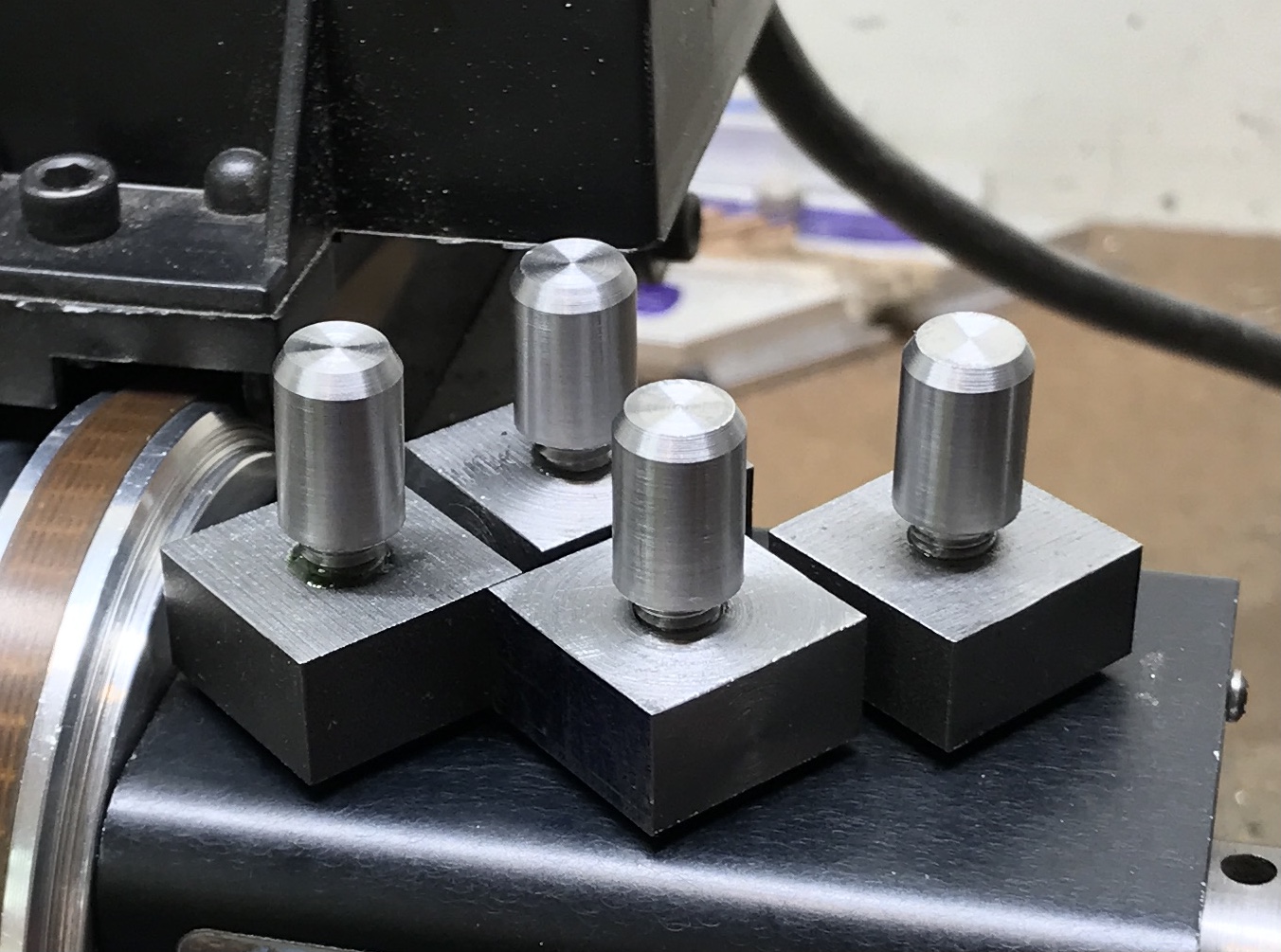
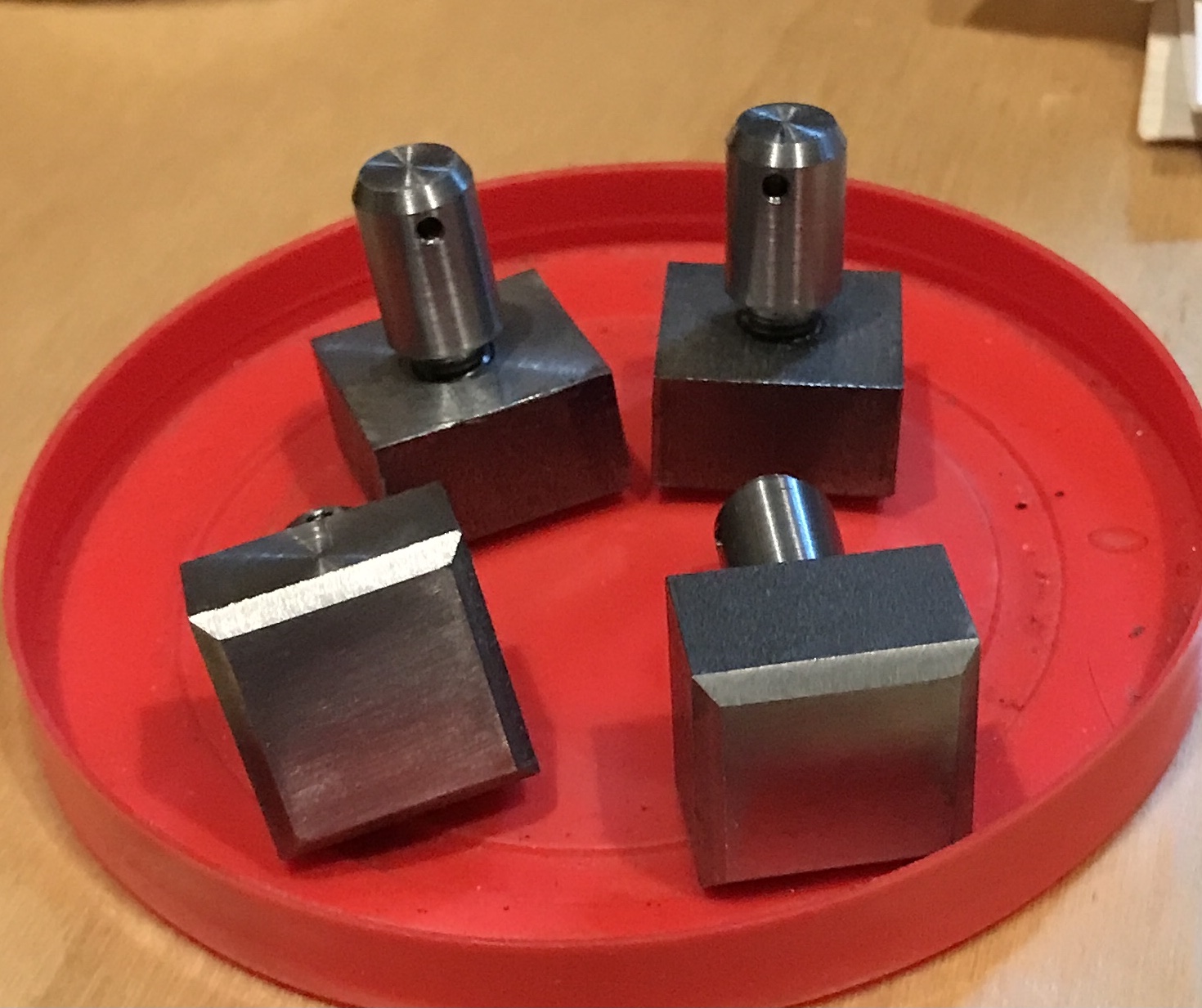
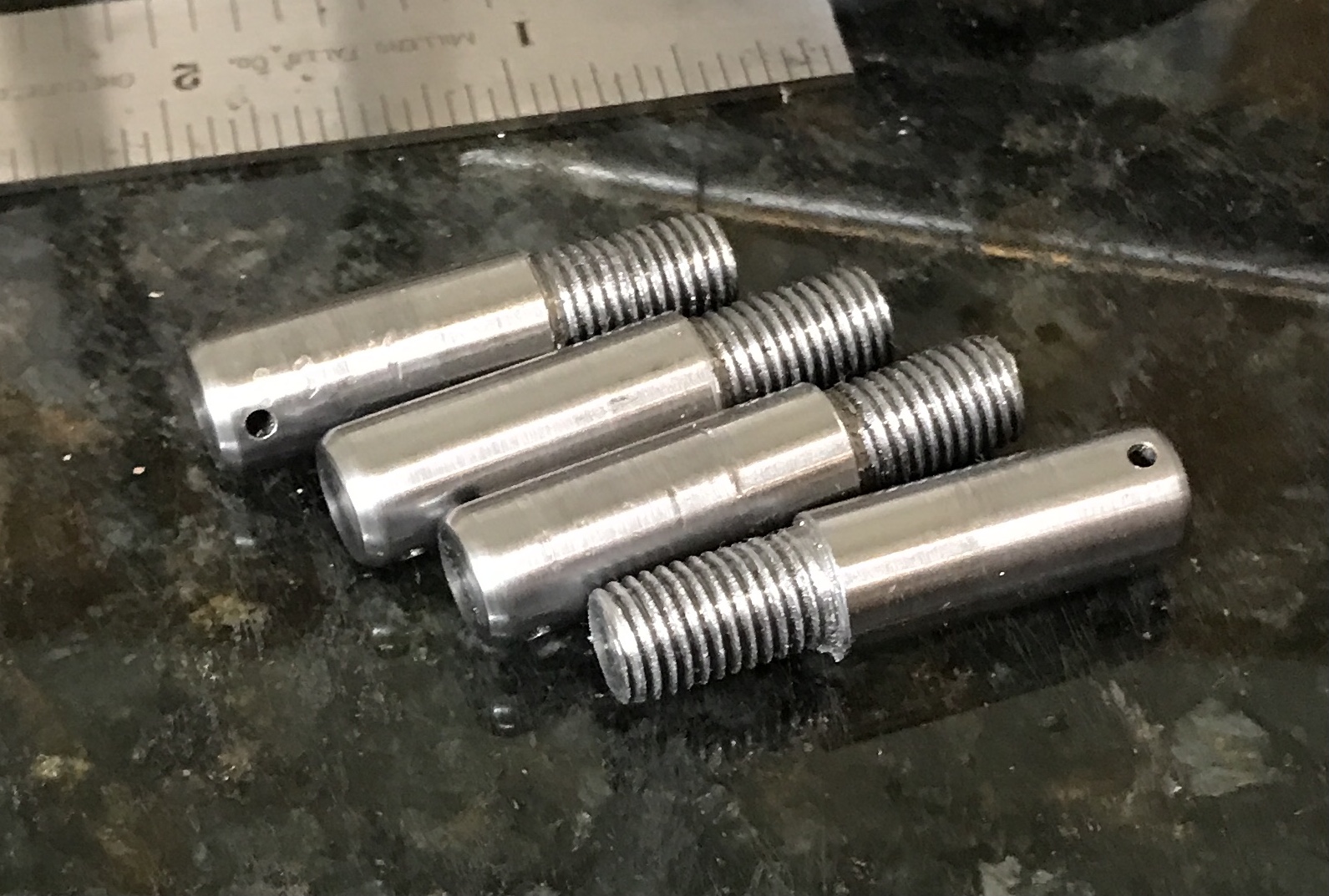
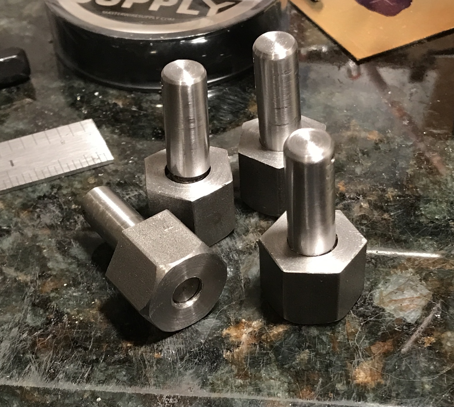
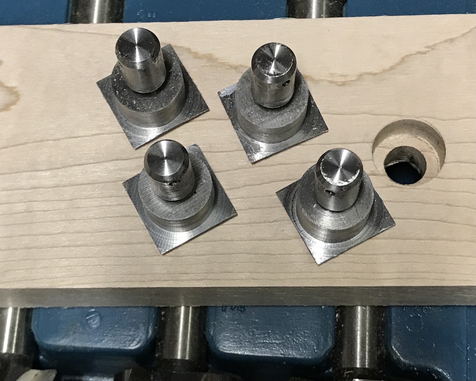
Screws were made for these blocks. A length of 3/8" steel hex was cut off with a hacksaw and held in the chuck. A 1" length was reduced to 3/8" round and a 0.40" length was further reduced to 0.25". This end was heavily chamfered with a file. The tailstock die holder was used with a 1/4-28 die to thread the end. The part was sawn off at ~1" with a hacksaw. This was repeated three more times. The rough cut ends were faced. The spindle was rotated 30° and a 0.30" chamfer was put on the end of each screw. The screws were put into the blocks with a drop of Loctite. The photo shows the blocks with screws installed.
One of the holes in the blocks was not on center. It was about 0.025" off in one direction. The hole was plugged with a screw, which was cut off after the Loctite dried. The block was faced and a second hole was drilled and tapped on center. Tapping the second hole was problematic as some of the screw's threads worked loose. A screw inserted with Loctite still worked. The first hole should have been opened to 5/16" or 3/8" and plugged to avoid this issue.
The screws need to be cross drilled for the wire. The wire is 20 gauge or 0.032" in diameter according to the AWG table in the metal working database in Devonthink. These wire holders will be on the corners of the top and wire will run from the screw hole down to both adjacent corners at 90°. Consequently, when the fitting is installed the hole should run across the corner, or from edge to edge. So the question is whether the blocks should be aligned with the corner or at a 45° angle.
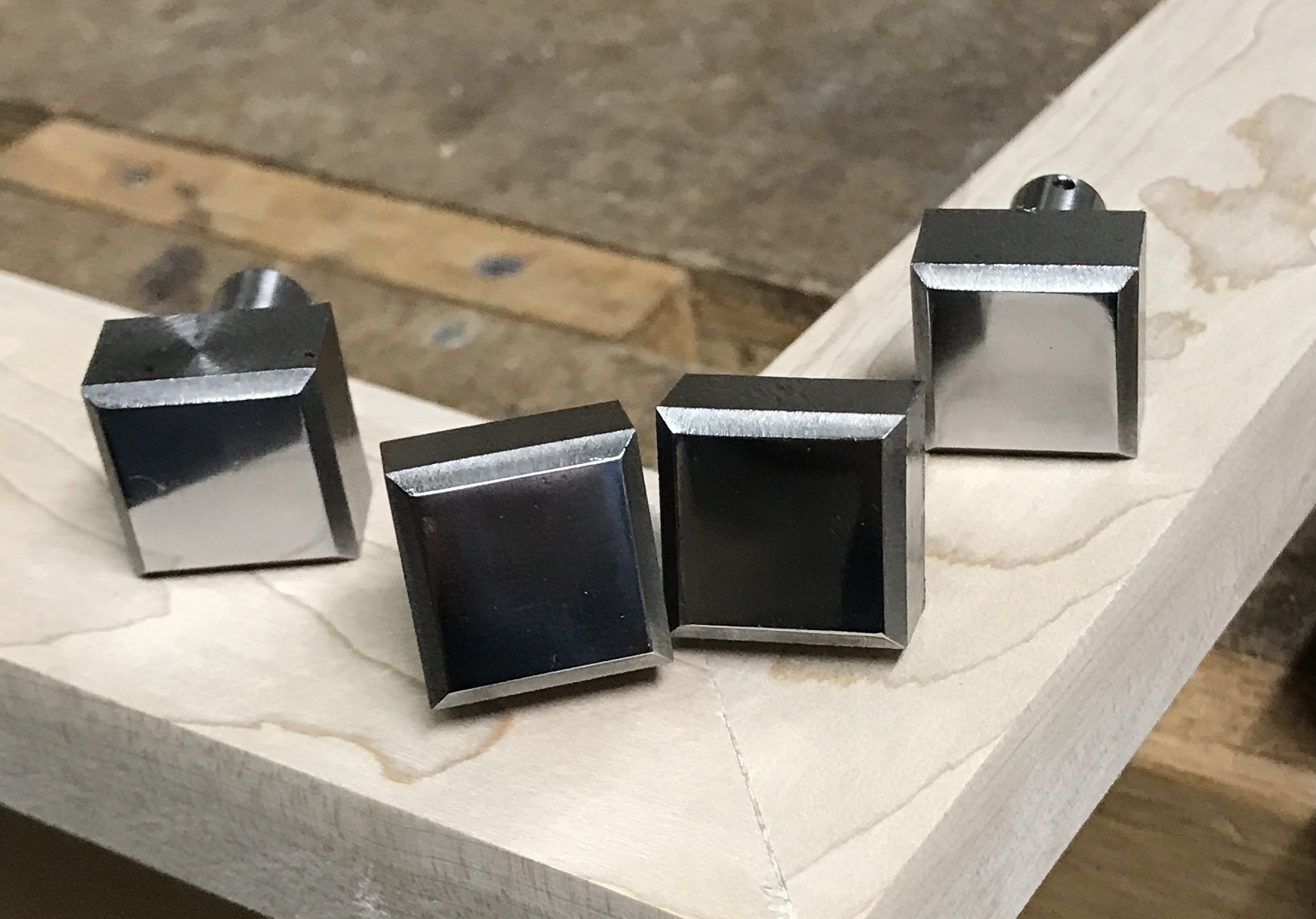
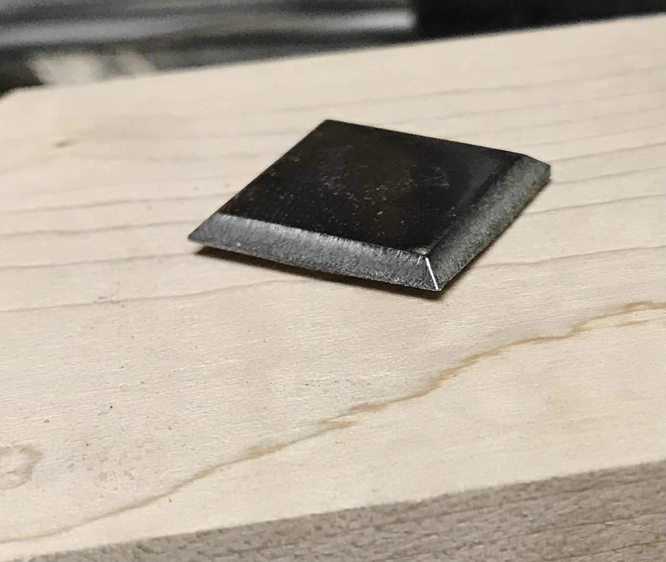
The faces of the four fittings were sanded with 120, 220, 320, & 400 grit sandpaper. After consultation with Rhea we decided that the fittings should be set at an angle with respect to the frame. This simplified cross drilling. The parts were held on their side in the vise and cross drilled on center and 1/8" in from the end. A #50 drill (0.070") was used. A slightly larger drill was used to chamfer the holes. The nearly finished "cufflinks" are shown below.
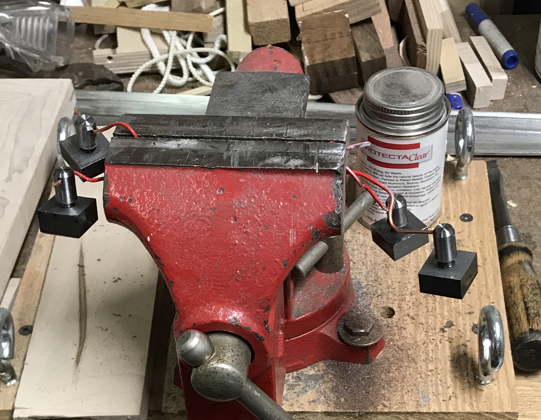
The top faces of the fittings were polished with the green rouge on a buffing wheel. This was followed by washing with soap and water, rinsing, washing with Na2CO3 solution, rinsing again, and a final rinse with acetone. The parts were hung on wires clamped in the vise and painted with Protecta-Clear varnish as seen in the photo below. After 45 minutes they were given a second coat.
There are still quite a few tasks remaining. The feet and adjusters need to be made. The connector design needs to be finalized with allowance for the attachment bolts. The connectors need to be shaped to the design. The holes and pockets need to made in the top and bottom. The corners of the top and bottom need to be finished along with finish sanding for the top and bottom. The top and bottom also require a finish of some type. And, of course, wiring and assembly will be the last task.
The adjusters were made this morning. Four 1.5" lengths of 3/8" drill rod were cut with a hacksaw. Both ends were faced. One end was chamfered 0.03" at 30°. The opposite end was reduced to 5/16" for 1/2". The end was chamfered with a file and 5/16-24 threads were cut with a die using the garage vise. There was significant scarring so the adjusters were sanded on the lathe up to 600 grit. The adjusters were cross drilled 1/8" from the chamfered end using the finger plate. The photo shows the four adjusters. About 1/4" of the adjuster will be exposed above the bottom frame for the wire to fit through. The 1/2" of threads will stick out below the frame and fit into a "foot nut" for adjusting.
The adjuster nuts will also serve as feet. They will be 5/8" tall and made from steel hex. They will be countersunk 1/8" and drilled/threaded through 5/16-24. As described four 5/8" lengths of 3/4" steel hex were cut off with a hacksaw. Both ends were faced in the lathe. One end was heavily chamfered with a file and the other was deburred. The non-chamfered end was center drilled and drilled up to an I drill. A 3/8" drill was used to countersink the hole. The four nuts at this stage are shown in the first photo below. The second photo shows the completed adjusters, tapped and assembled.
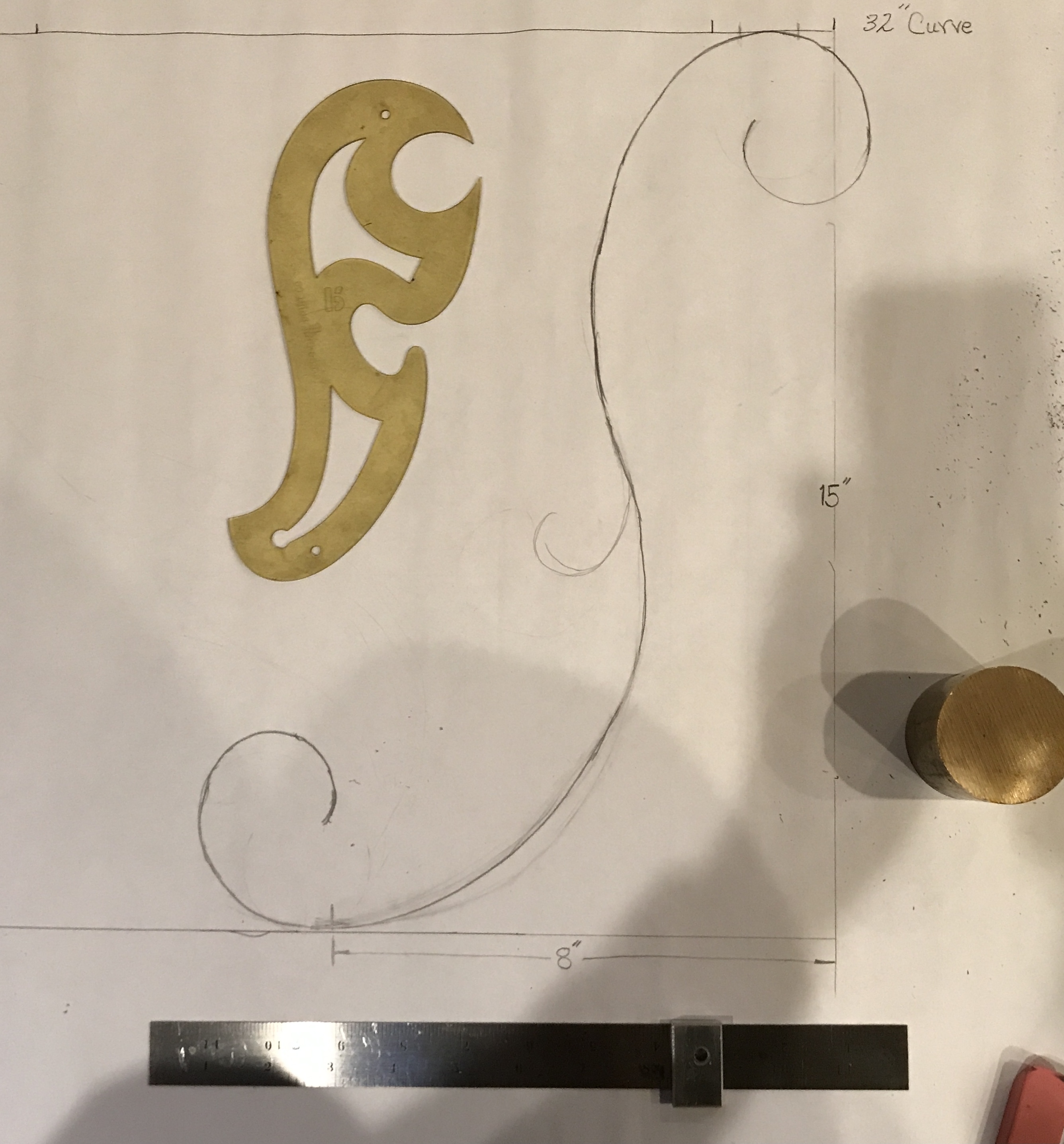
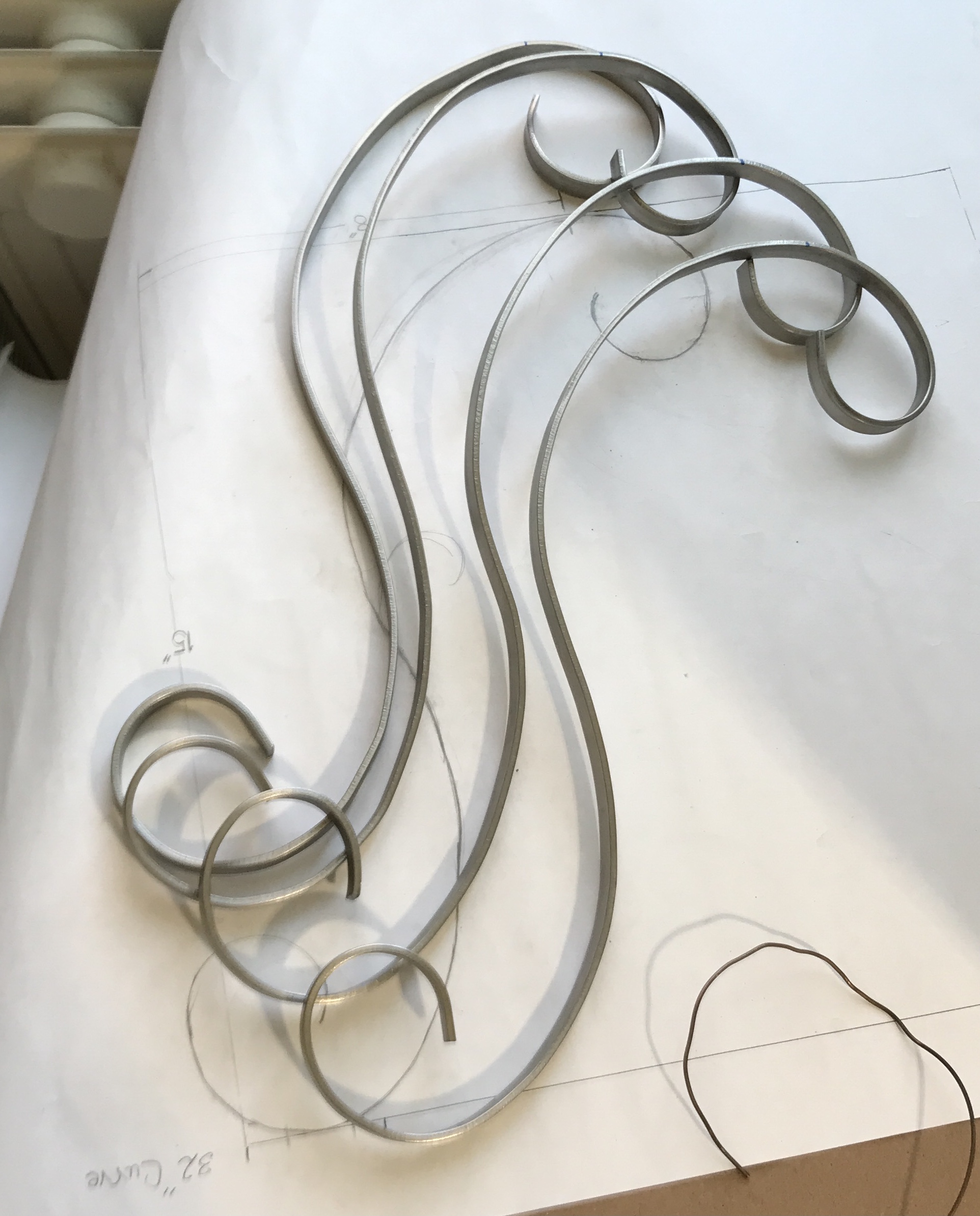
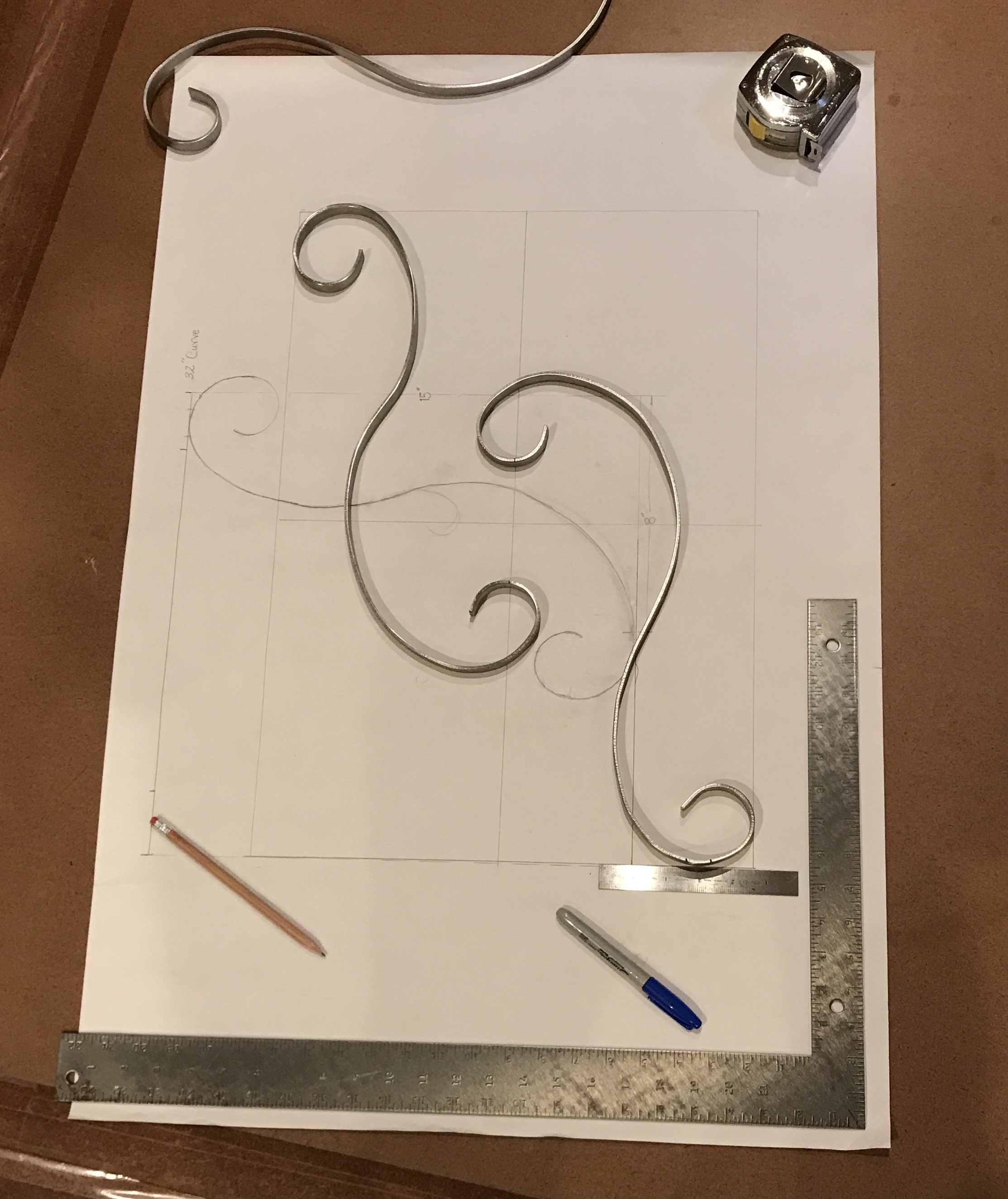
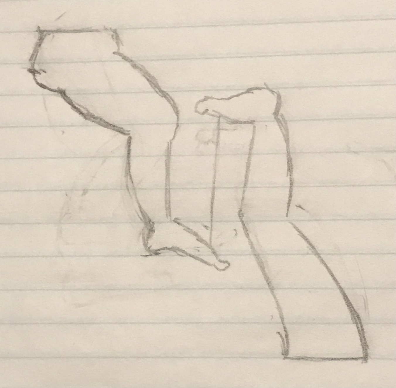
A tentative curve was sketched out. The requirements are that it spans at least 7" X 15" and provides enough room for two bolts to hold it to the frame. A 2" brass round and a French curve were used as guides for the ends. An HDMI cable was used to determine the length of the curve. It is 32" long, whereas the stainless steel bars are 36" long. The extra may be used for a small flourish. The picture shows the planned curve.
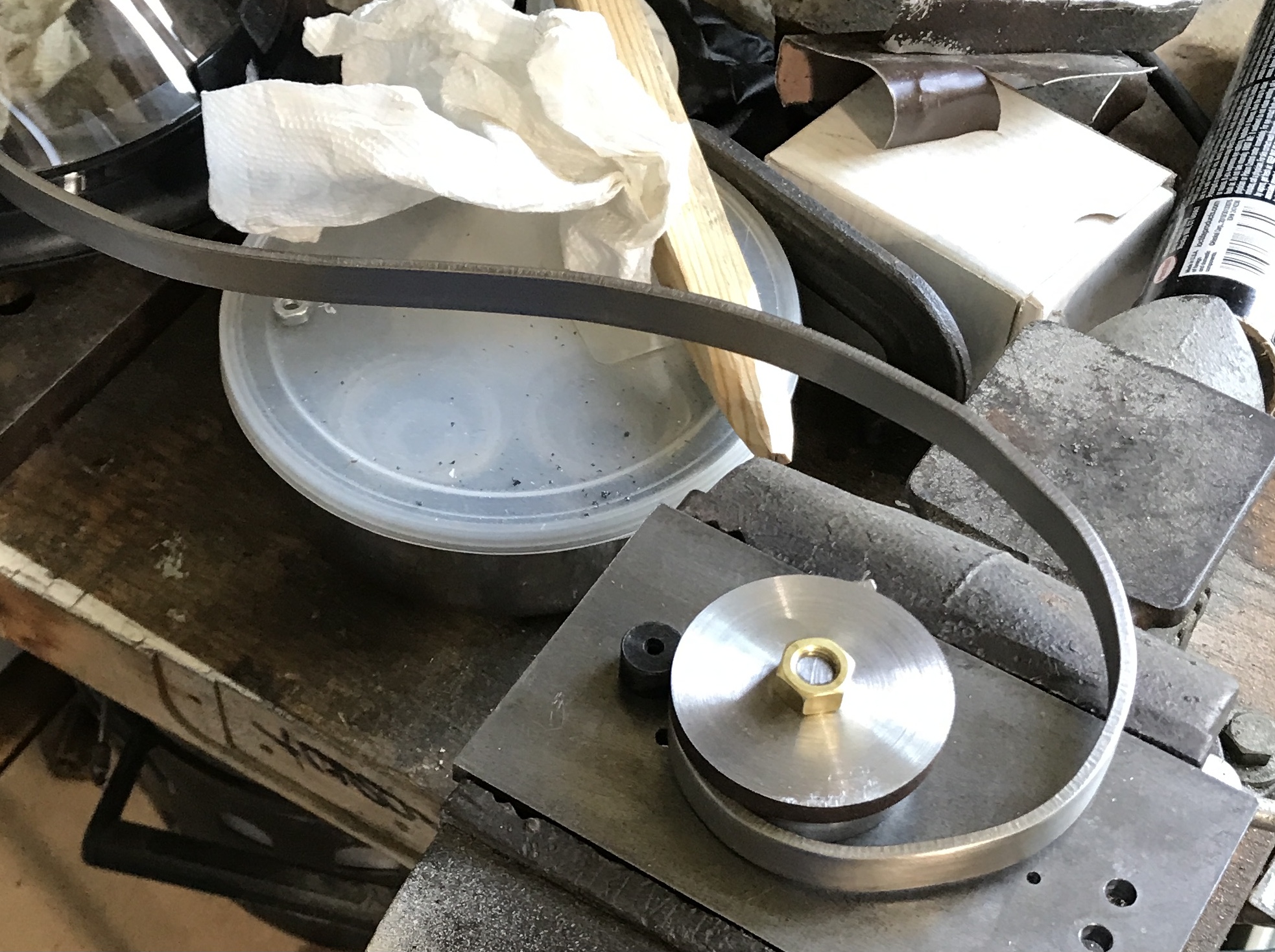
Bending is my new hobby! Maybe not. The first tight curve was bent by hand using the vise. It was very difficult to get it tight enough. An old bending jig that had been repurposed for aligning and drilling the holes in the water droplet rings was pulled from the drawer. It has a 5/16-24 screw in the middle and a 1/2" stop on a 1/4" post. A 1 3/4" bending mandrel need to be made. A piece of 2" scrap steel was located. It was reduced to 1 3/4" for slightly more than 1/2" after facing one side. The other side was then faced leaving about 3/16" of 2" stock. A 5/16" hole was drilled through the center. This work was done on the South Bend lathe. A 1/4" hole was drilled and reamed 1 1/4" from the center of the screw in the flat stock for the anchor. The photo below shows the completed bending jig.
One end of the steel bars was first bent into a tight semi-circle with the jig. The bulk of the curve was then bent in stages by hand using the vise as a fulcrum. The best curves resulted from making a small bend, moving the metal 1/2" and repeating multiple times. A small amount of bending was done and the bar was checked against the plan. Corrections were made as needed. A convenient spot on the bar was marked and aligned with a mark on the plan during each measurement. The second tight curve on the opposite end was bent with the jig after measuring and cutting off the excess bar (2-4"). The first photo shows a tight curve being bent on the jig. The second photo shows the four completed connectors.
Bending is very physically challenging! At least there was improvement with each iteration.
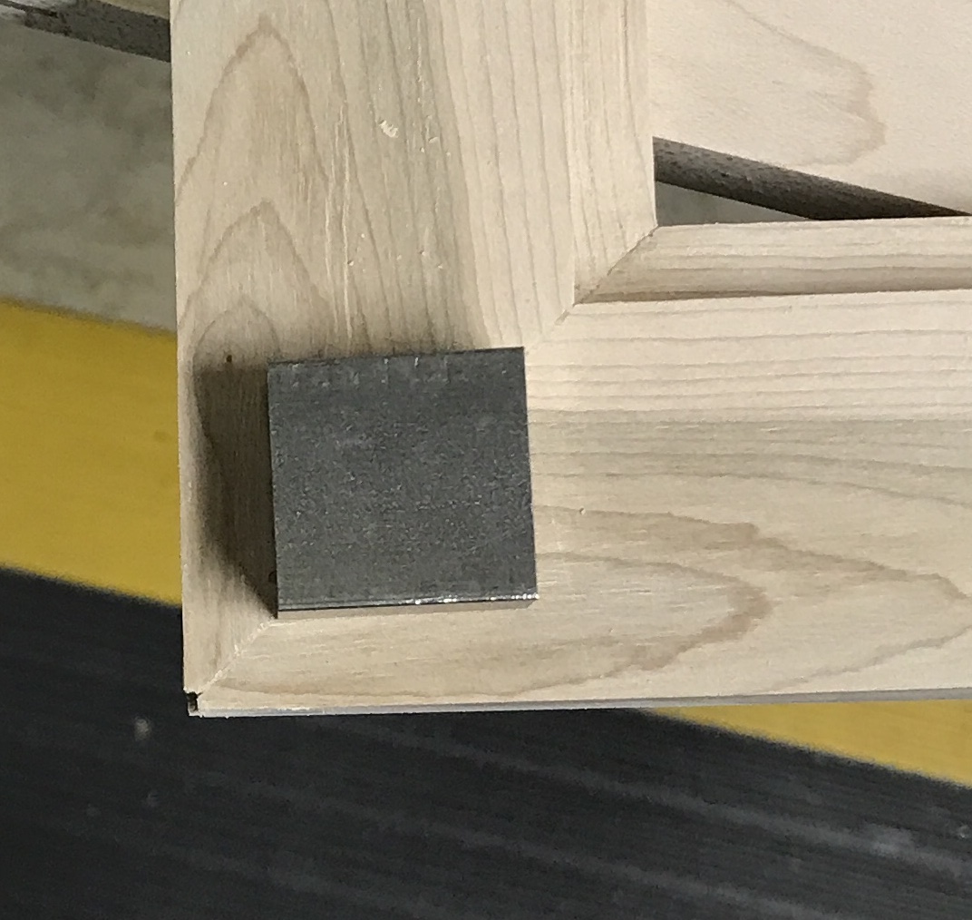
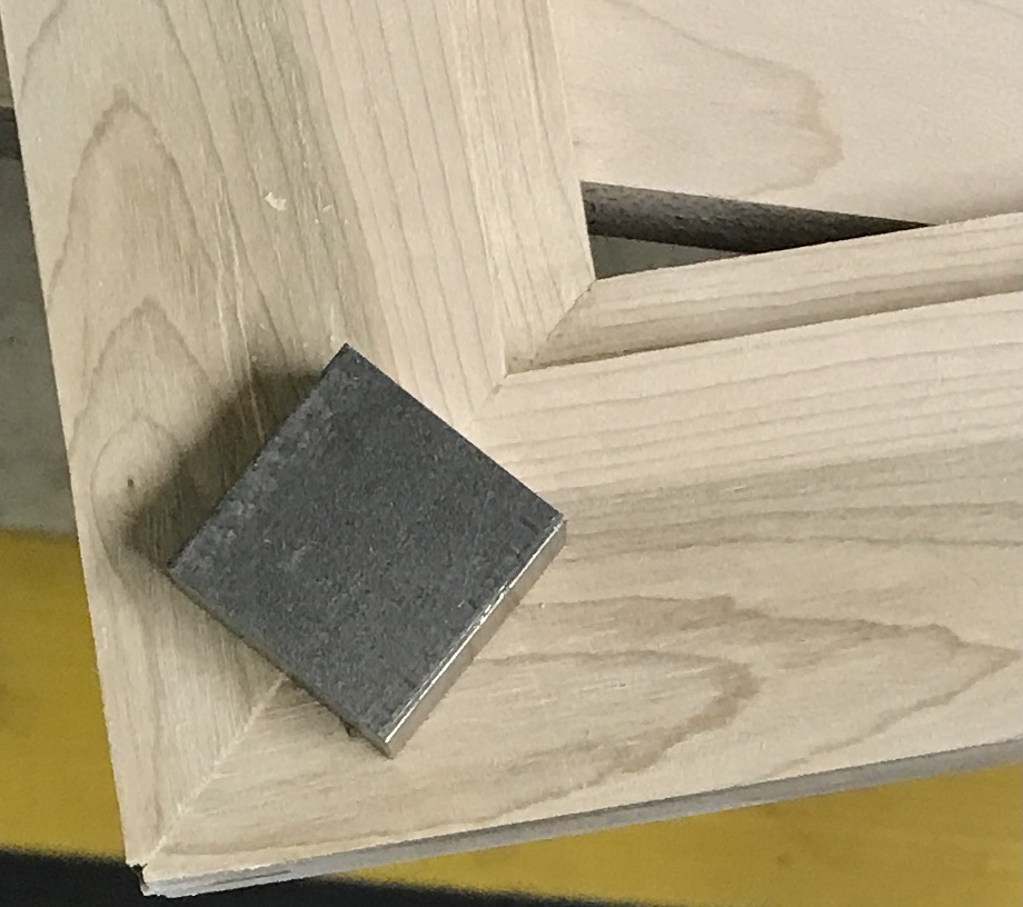
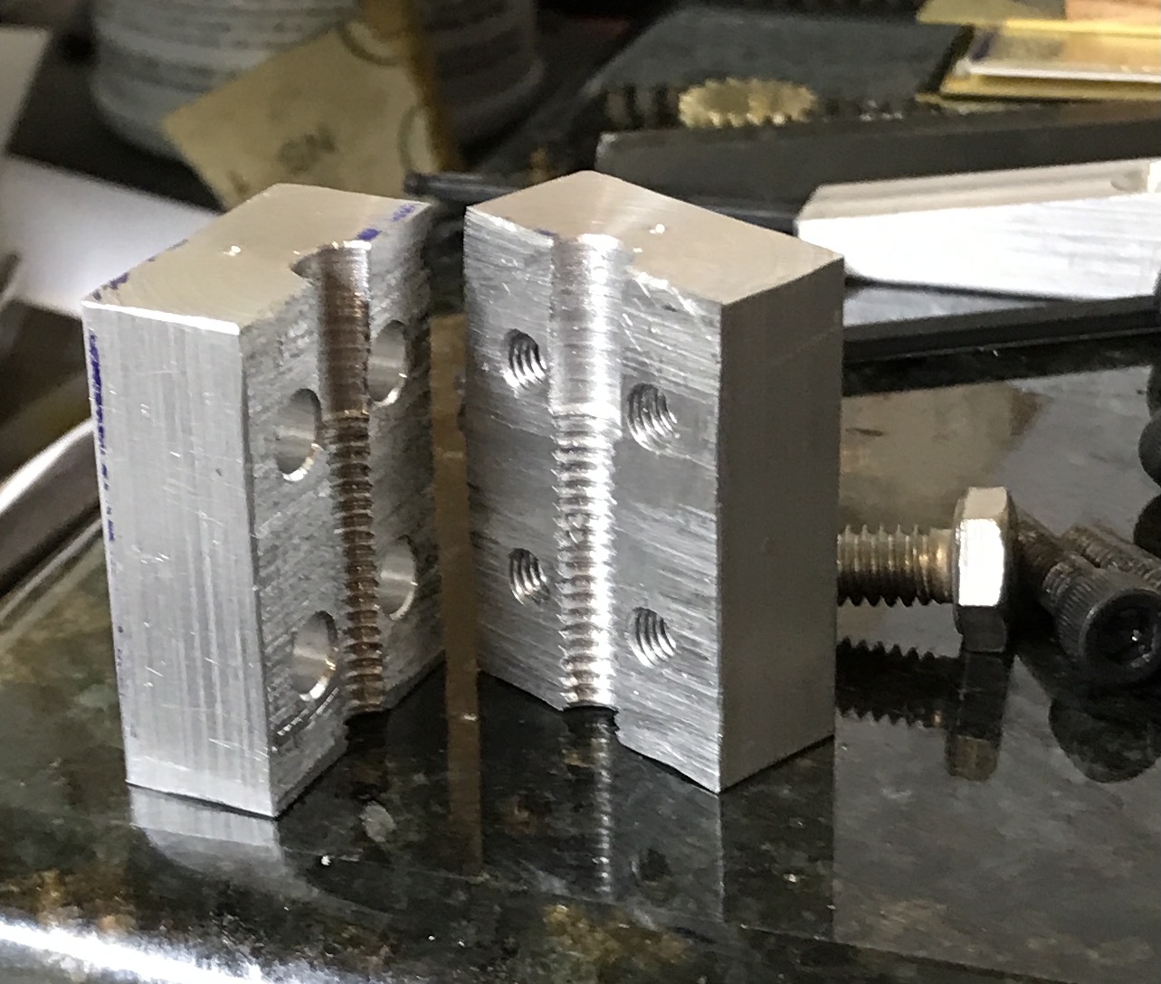
A trial was carried out to determine if chiseling a hole for the top wire holders would provide a tight fit. A scrap of the hard maple was located and marked for the hole. A 3/8" hole was drilled with the drill press. A wire holder was set in the hole and clamped. A marking knife was used to outline the block as close as possible. A 5/8" chisel was then used to set the knife wall and to remove the material in the square opening. This went well, especially after sharpening the chisel on 1000 grit paper. It took about one hour to make a 3/8" deep square hole. As the pictures show the hole is a loose fit with the wire holder.
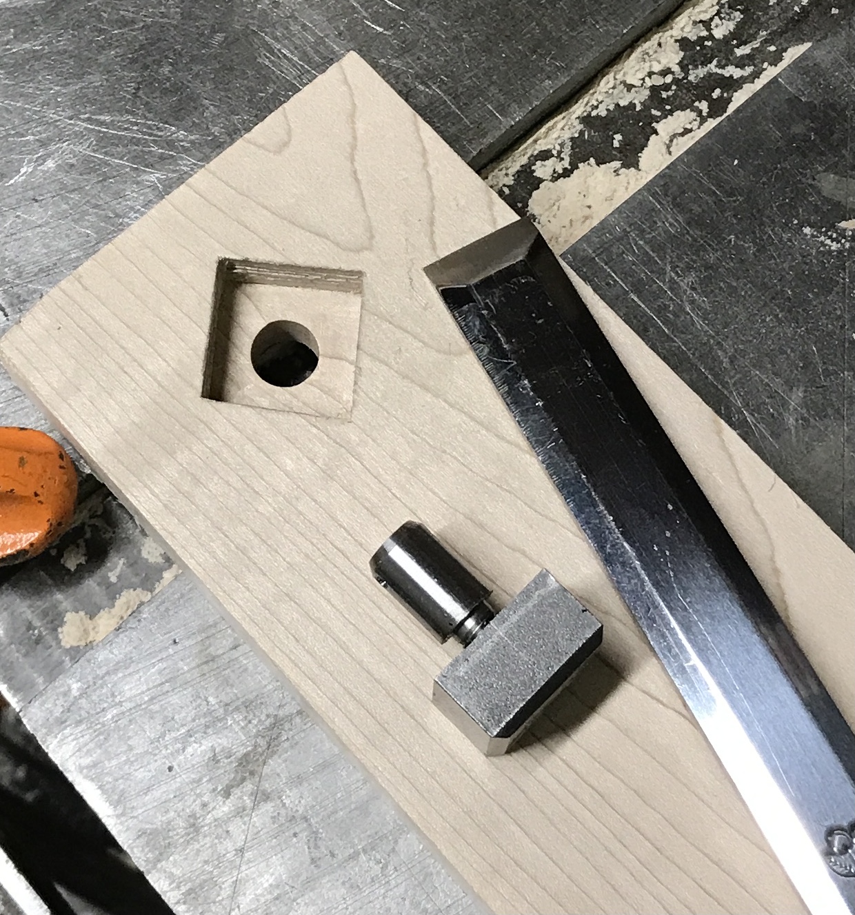
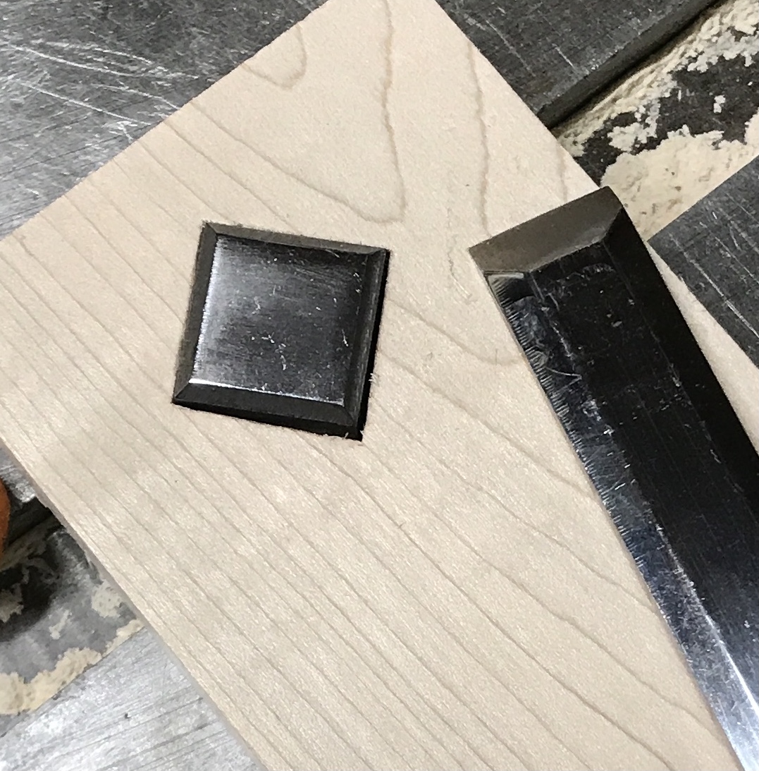
If this were a joint the gap could be hidden with sawdust in the glue. No glue will be used to hold the wire holder in the pocket, so a different approach must be designed. Chiseling out the openings would be a waste as they will never be seen. A round opening would be much simpler as it could be made with a drill. My first thought is to put the wire holders in the lathe and cut the square round leaving only the mitered part square. A 5/8" hole would be hidden beneath the 3/4" square. The only problem with this approach is that the wire holder could turn. This makes it difficult to align the holders as needed for aesthetics. A little epoxy would negate this issue.
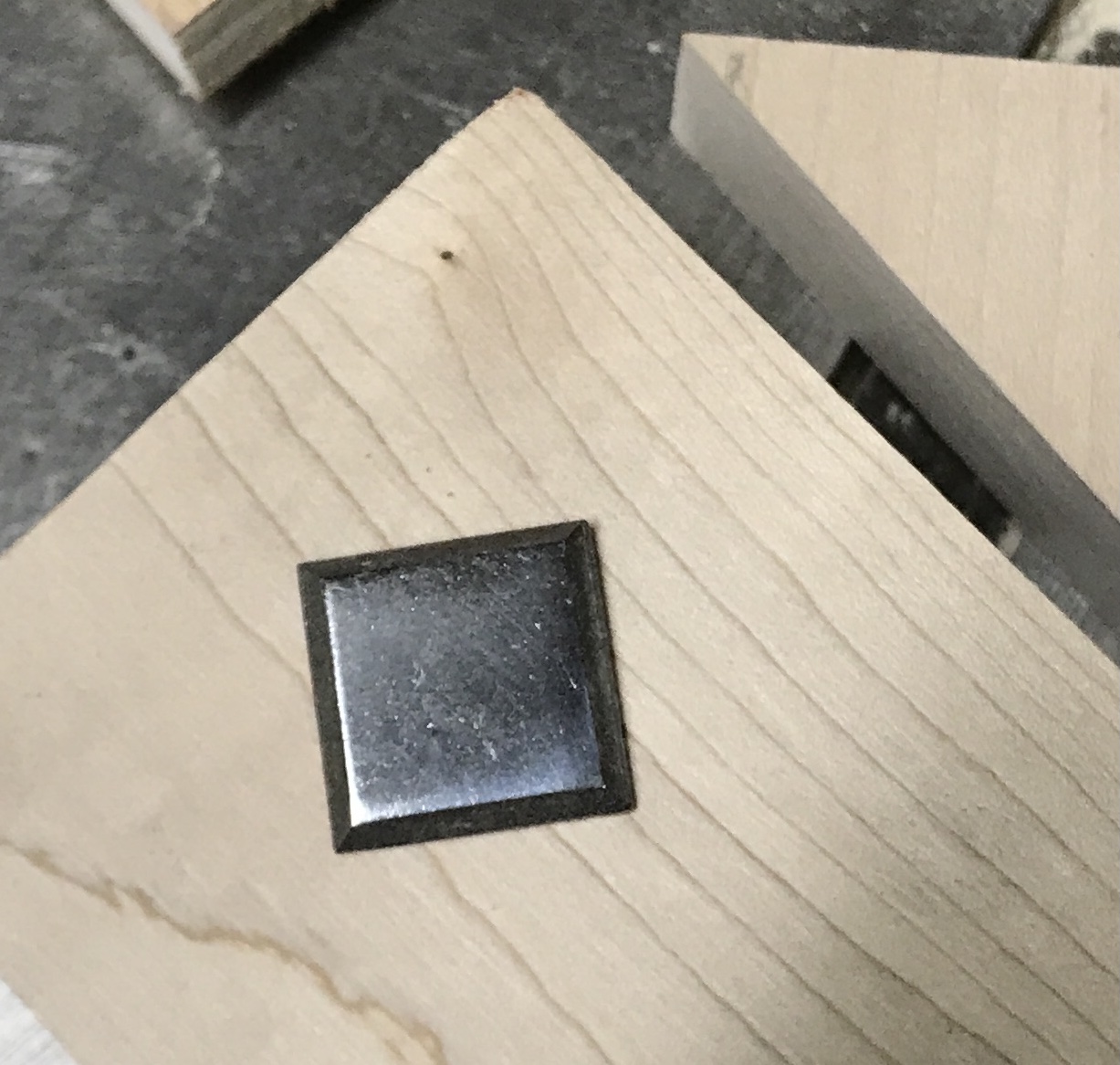
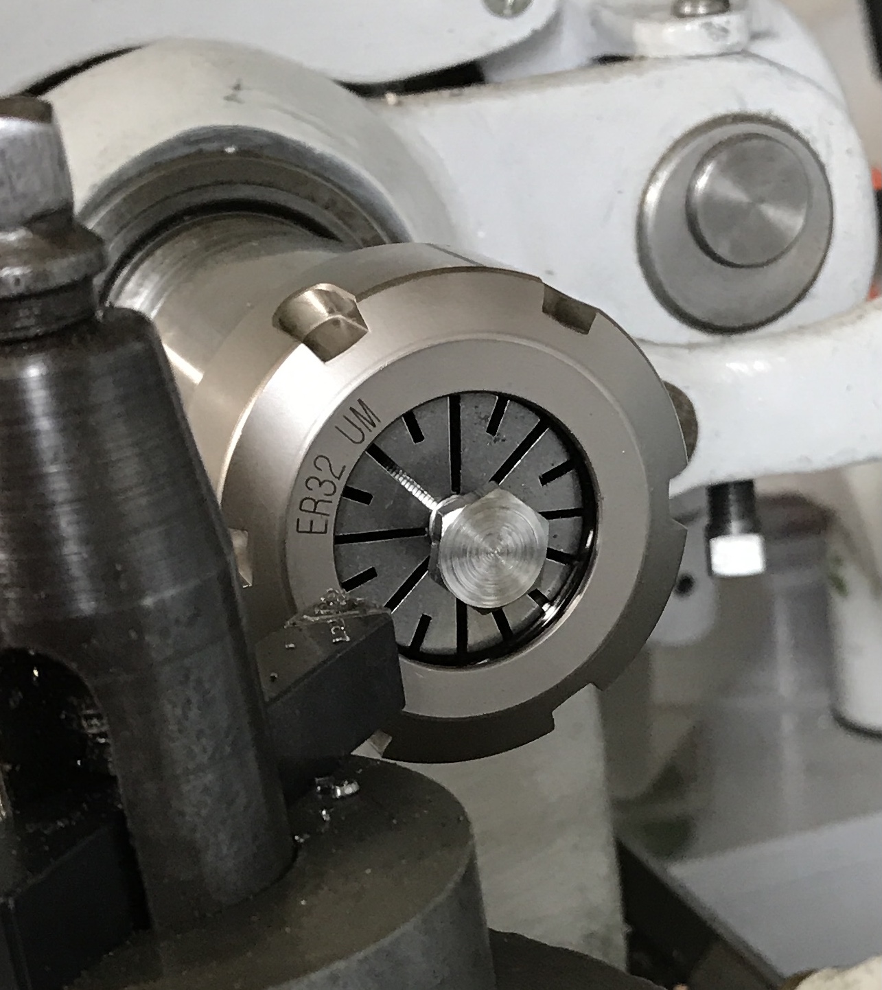
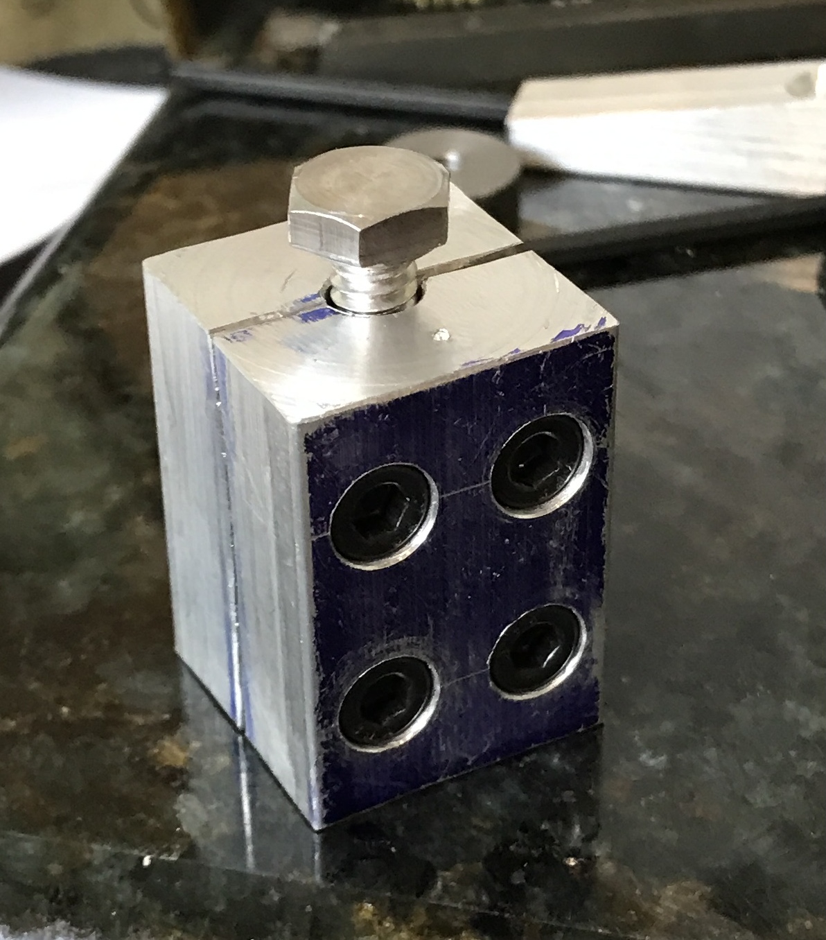
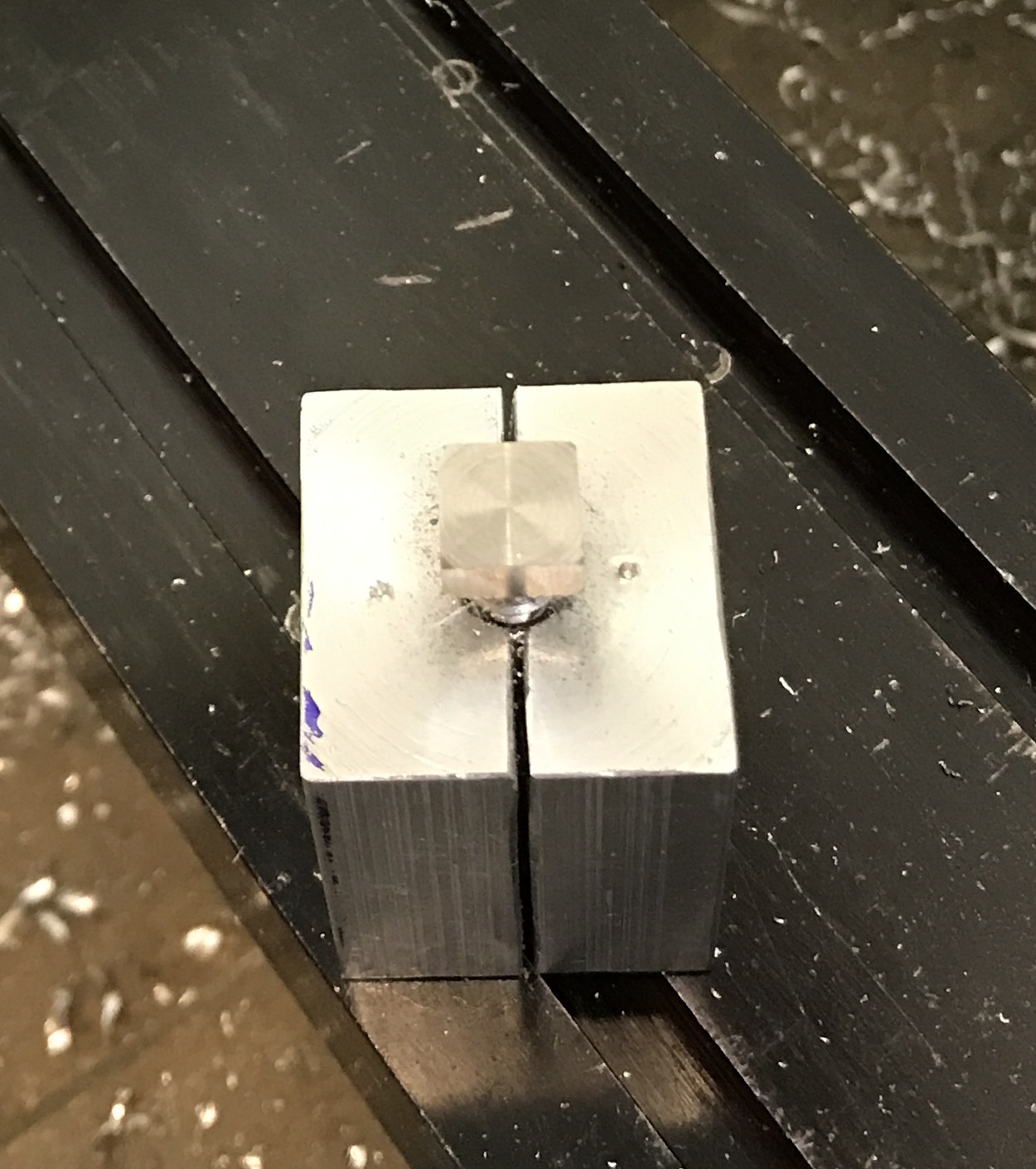
The wire holder was held in the chuck by the screw end. It was difficult to grip this end tight enough for the interrupted cutting. A stop was used to set the depth of cut. Using a left hand lathe bit most of the square was reduced to round and then to 0.625". Because the screw is not perfectly concentric the cut is not all the way to the bevel on all four faces. After drilling a 3/8" hole followed by a concentric 5/8" hole in the scrap wood the reduced wire holder was hammered into place. The first photo shows the nice fit from the top. The second photo shows the gap on one side due to the asymmetric cut. A little work with a file minimized the gap.
The remaining three wire holders were treated similarly. They were all reduced to 0.623-0.625". One had a screw that was even more out of line. A small piece of aluminum was used to shim near the end of a jaw to better align the square part of the holder. None of these three needed filing.
After a brief delay for a booster, its accompanying 24 hour illness and grandparents day, I am returning to the legless table. I came home from Menards with 1 1/4" long 1/4-20 stainless steel screws and matching stainless lock nuts. The heads of the screws are 0.429 across the flats. After a little math the depth of cut to make the largest square (where two sides of the square are parallel to two sides of the hexagon) is 0.079".
The screws have raised letters/numbers on the heads, which need to be removed. The plan is to turn the screw heads flat in the lathe using a collet. Then using the four-sided indexing block the heads will be squared up and mitered with the Sherline mill.
The facing on the South Bend lathe went quickly once the chuck was replaced with the collet holder. Ten screws were faced flat; two more than the requisite eight to be milled square.
The screw was transferred to the Sherline three jaw chuck with a scrap of aluminum for rigidity. The chuck was screwed to the square indexer and held in the vise. A 5/16" end mill was used to remove the required 0.079" from one flat face of the head. There was tremendous chatter. The screw is not held tightly enough in the chuck. A jig is needed.
A 1.5" length of 1" square aluminum stock was cut off. It was held in the four jaw chuck and both ends were faced parallel. It was drilled through on center with a #7 drill and tapped 1/4-20. In order for the tap to go all the way through, the top 1/2" was drilled 11/32". This was a good fit on the purchased screws.
Four holes were laid out on the side of the jig. These holes were 1/4" in from the long side and 3/8" in from the bottom and top. The holes were drilled through for a 10-32 screw with a #21 drill. The top was countersunk for the socket heads with a 5/16" drill 0.2" deep. The holes were tapped 10-32 in the vise. The jig was marked on the top and one side for the hacksaw cut. The jig was cut in half by hand (whew!). The jig was cleaned up with a bit of filing and deburring. All holes were chamfered. After assembly an error was discovered and fixed. The threads in the four holes on the screw head side had to be removed. A 10-32 clearance drill, 7/16", was used to drill out the threads on this side.
Of course the jig is no longer square. After tightening a screw it is necessary to make sure the screws are all evenly tightened. When this is done properly the difference between dimensions is only 0.010".
The jig was tried out this morning. A screw was held tightly in the jig and placed sideways in the vise on the milling machine. A flat side was milled until the new flat was about 5/16 in width. This was repeated on the opposite flat and then on the two adjacent pointed sides. These were milled until sharp corners formed. The final product as seen in the photo is 0.325" in one dimension and 0.335" in the perpendicular dimension. There is little difference along either dimension.
Shifted to production mode and cranked out the next seven square headed screws. In contrast to the calculation 0.050" was removed from the two parallel faces and 0.090" was removed from each of the angled sides. This gave very square heads. It took about fifteen minutes per screw, including some deburring. Using the same fixture the screw heads were lightly chamfered with the milling head rotated 45°.
The square head screws need to be polished and then it is time for assembly!
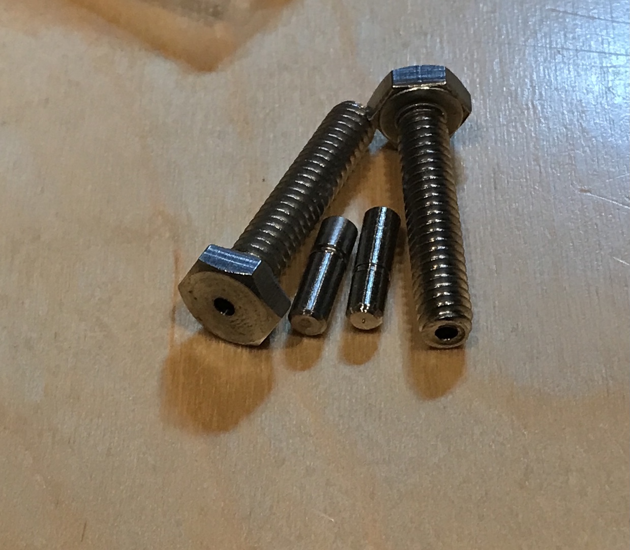
Not quite yet. Four more fittings are needed to hold the wires between the center wire supports. The two fittings on the top will just be stainless steel pins with a groove for the wire to run around the pin. The bottom fittings will be screws with a hole drilled through lengthwise to serve as tension adjusters. Two pins were made about 3/4" long and chamfered on both ends. A groove was cut in the pins for holding a wire. Two of the faced screws were drilled through with a #40 drill in 0.05" increments. Both are shown below.
It is not clear how best to align the bent connectors between the table top and bottom. The alignment and orientation determines the locations of the bolt holes. The unattached ends of the connectors need to be located directly over each other. This is set by the rotation of the connectors around their attachment point. The plan is to sketch out the table top and bottom on a large piece of paper. This will be used to define the bolt hole locations.
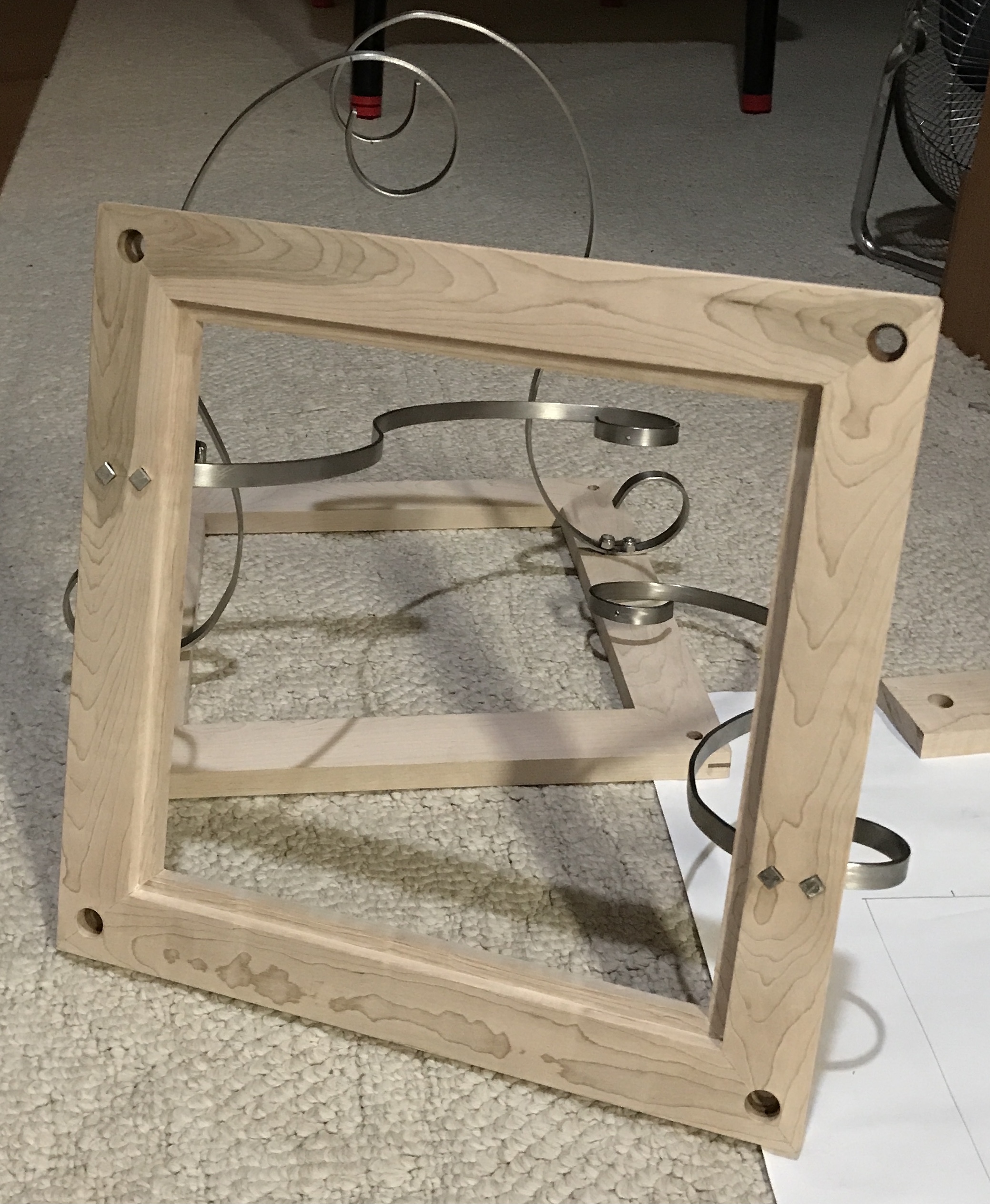
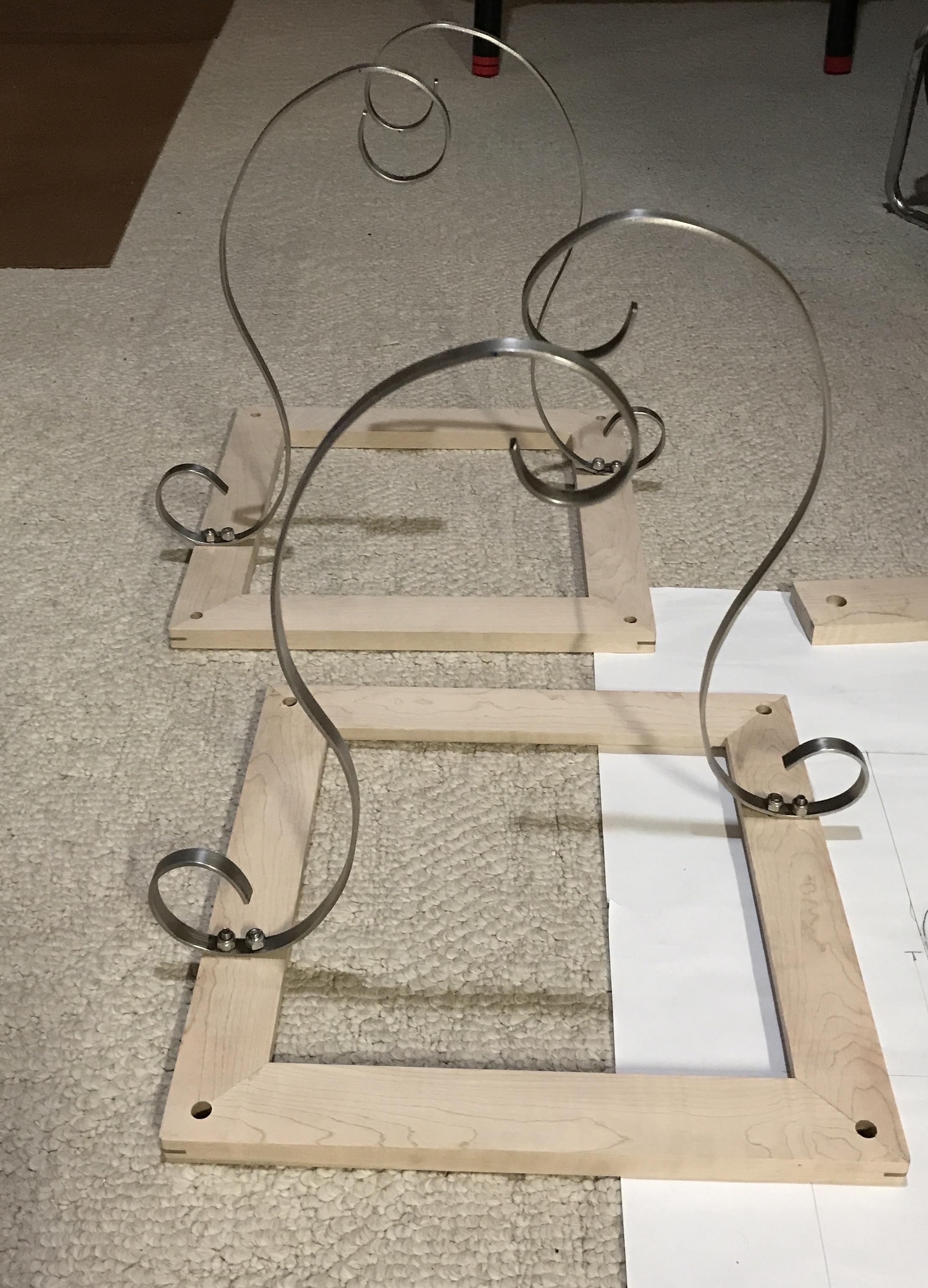
A table outline along with centerlines was sketched out. The inside measurement from top to bottom was set at 22". Two connectors were set in place and aligned to end, one directly above the other on the centerline. The holes for the center wire were marked. Holes for the two bolts holding each connector to the frame were marked 3/4" apart on either side of the spot where the connector contacted the top or bottom line. Both sets of connectors were marked in this way: one in blue and one in black. The marks needed to be redone when I realized that the screw holes would be drilled outside of the frame! When in place the outside of the connector's curve sits well outside the frame not as seen in the picture below. The through holes in the frame should be centered across the width of the frame and 3/4" apart.
The holes in the steel were drilled. The holes for the wires were drilled with a 1/8" carbide drill. All holes were drilled with the cordless drill while the connector was held in a vise. The four holes for the wire took over an hour. The drilling was done for thirty seconds followed by a similar length rest. Plenty of cutting fluid was used. The 304 stainless steel is tough stuff!
The holes for the bolts were also drilled first with the 1/8" carbide drill. This went faster when I realized I was drilling too slowly. Web recommendations said to drill slowly. I took them too seriously. In any event the next eight holes took less than hour. Opening these holes to 9/32" was saved for another day as my arm was kaputt!
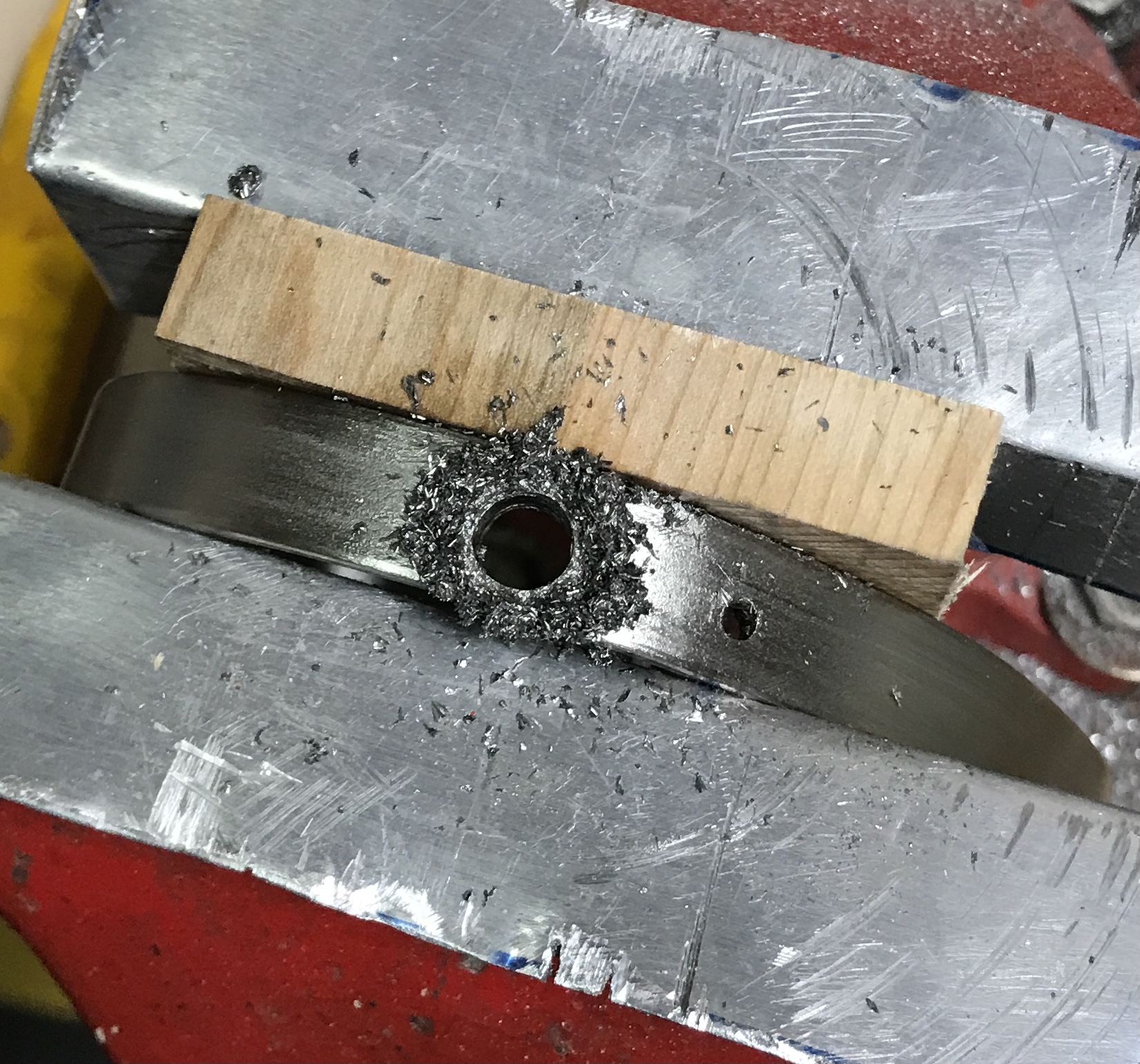
Back to the project after a short break taking care of the grandsons and dog for five days. Enlarged two holes to 9/32" with another carbide drill. It is very slow, but can be done. The drill catches when the bit is almost through. I found it necessary to finish the holes by driving a punch through with a hammer. The large burr was removed by filing. The photo shows the first enlarged hole. The block of wood is needed to move the connector away from the table, so it doesn't get bent.
The remaining six 9/32" holes were drilled this morning. The drill was chipped so a new drill was used. This went faster, but was still a lot of work, about five minutes per hole. The punch was used to "finish" the holes. A round file deburred all six holes. The photo below shows the connector ends with the through holes.
The photo above also shows a small square chiseled opening in the wood scrap used earlier. This was a trial run for the screws that will hold the connectors in place. It was drilled 9/32" and a screw was placed in the hole. The square head was outlined with a pencil. The edges of the hole were barely visible, when the screw was in place. A square opening was chiseled out with the smallest chisel. The screw set nicely into this opening. The hole should probably be drilled with a 17/64" drill to avoid visibility.
The holes were laid out and drilled this morning. The holes for the wire holders that sit in the corners of the frames were drilled 3/4" in from each side. The bottom holes were drilled with a 3/8" drill followed by opening with a 25/64" drill. The holes in the top were drilled 3/8" followed by a 5/8" Forstner drill bit to the depth of the bit. These holes were not completely centered, so the 3/8" hole was opened with a 7/16" drill.
The four sets of two holes for the connectors were matched to a connector and drilled with a 9/32" drill. They were set in 5 1/8" from the corner and were marked to fit the distance between the holes in the connectors, approximately 3/4". The four connector holes on the top were marked and squares formed with a chisel about 1/16" deep. (The bolts in place did not reveal the hole.) After screwing the connectors in place with the bolts and nylon lock nuts two photos were taken.
The frames need to be finished before the table is wired together. I don't think I want to wire it twice. Time for some sanding. Sanded up to 220 on bottom and top of both frames. Rounded over the long edges as well as the corners. Stain is being explored on a similarly sanded piece of scrap. After staining a scrap and also trying tung oil I checked online for recommendations. The stain is too heavy of a look for this table. Many woodworkers liked the white maple look and recommended lacquer as the only finish, because it does not turn yellow over time. I will purchase a spray can from Lowes, when I purchase the fungicide for the lawn.
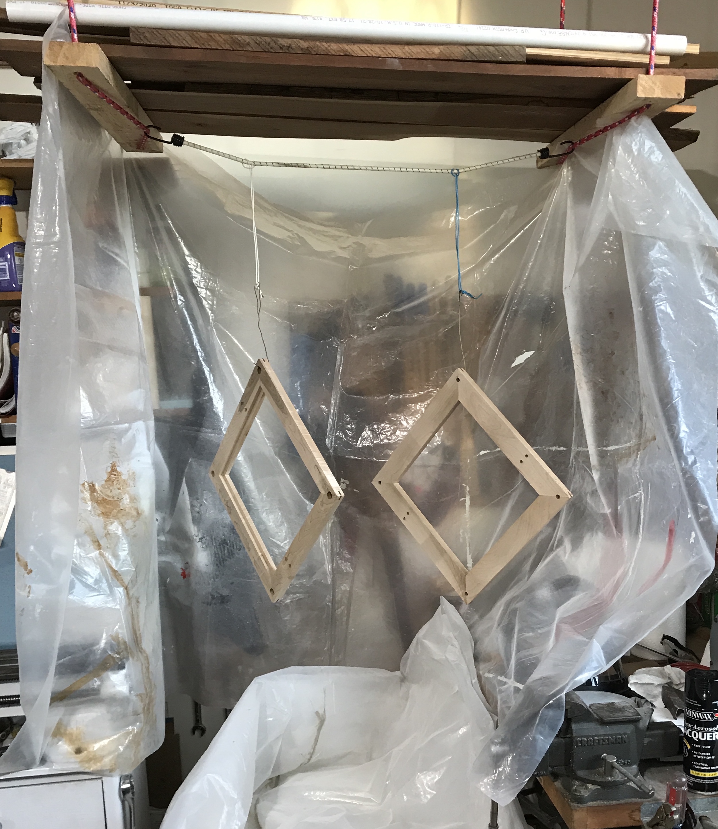
Purchased five 10 lb bags of fungicide along with Loctite and Minwax spray lacquer. After sanding to 320 grit the frames were wiped down with mineral spirits. The frames dried for ten minutes and the first coat of lacquer was sprayed on. Thirty minutes passed and a second coat was applied. Six coats were applied in the temporary spray booth shown below.
The frames were gently sanded with #0000 steel wool. This gave a very smooth finish. The connectors were installed on the frames. At this point I realized that the bottom connectors needed 9/32" holes if the adjusters were to be used. Thinking through the adjustment process makes me question their utility.
In any event it is time to determine how much wire is to be used. The wire holders are 13 3/4" apart. There will be approximately 20" from top wire holder to bottom wire holder. Consequently, each wire running from corner to corner is 24 1/4" long. There are eight of these. Two wires will be used to cover these eight strands. Four strands is 97". This puts the connectors about 5" apart.
After putting the two wires in position along with the wires between connectors, it was nearly impossible to adjust the tension as needed. Switched to four wires and was able to adjust the tension so that the table was level and not twisted. It seemed reasonably solid, but when I put the heavy plate glass in place the table immediately twisted! I don't know if that is because there is insufficient tension in the wires or if something else is the culprit. After a bit of study the twisting seems to be from at least one wire slipping through the bottom wire holder. All of the wires are attached to the top and each wire goes through one bottom holder. Wiring again with eight wires may be the solution.
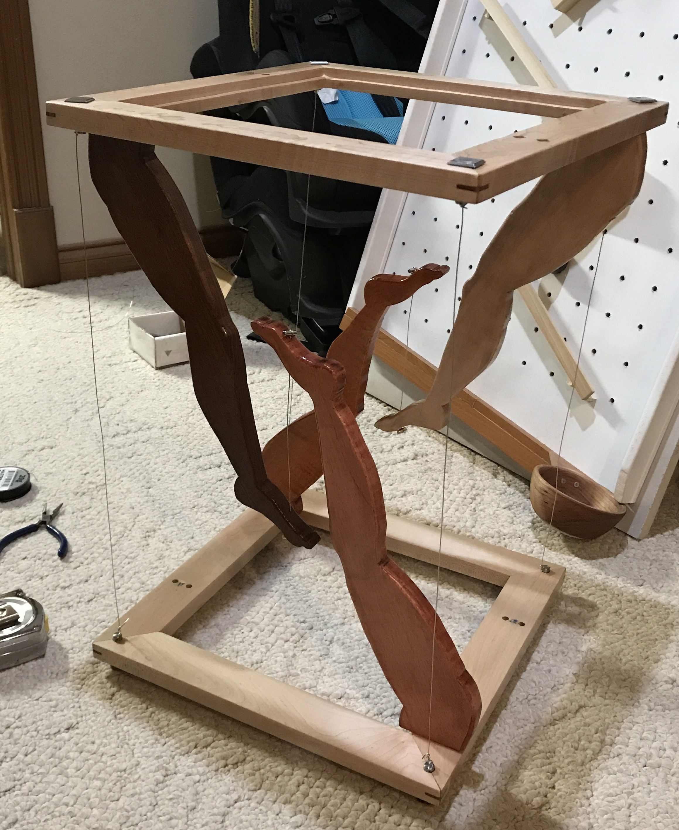
The table is not functioning properly. As the wires are tightened the table twists. One corner is also pulled lower than the other three. The pictures below attempt to show these anomalies. The middle supports were cross-wired to alleviate this twist, but to no avail. The table is reasonably solid. Notice also how close the supports approach each other.
After a couple of weeks thinking about the table I am convinced that the problem lies in the position of the supports. They are too close together. There should be less twist if the supports are spaced wider on the frame. Of course, testing this theory requires drilling new holes in the top and bottom frames, as well as plugging the old holes.
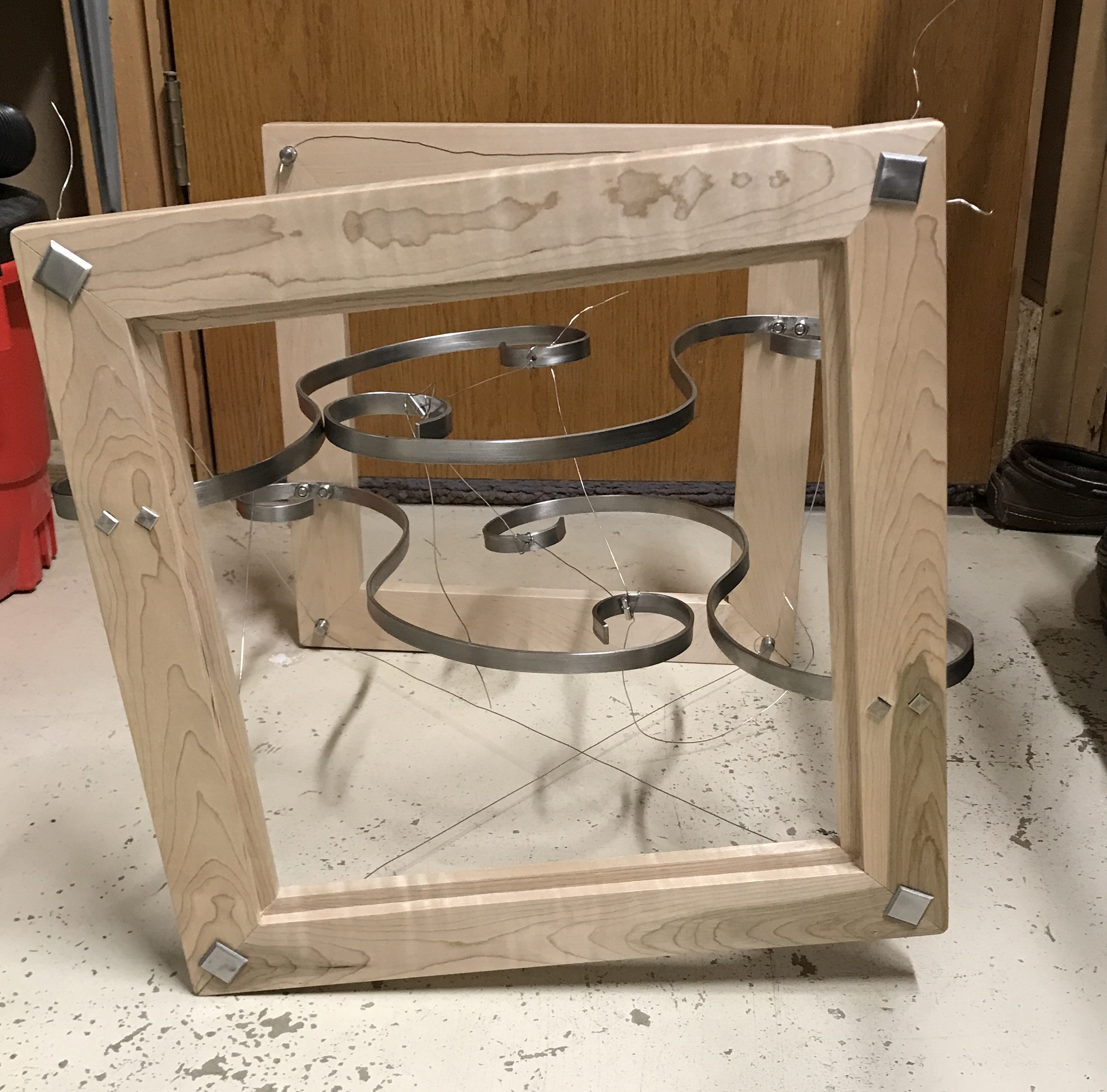
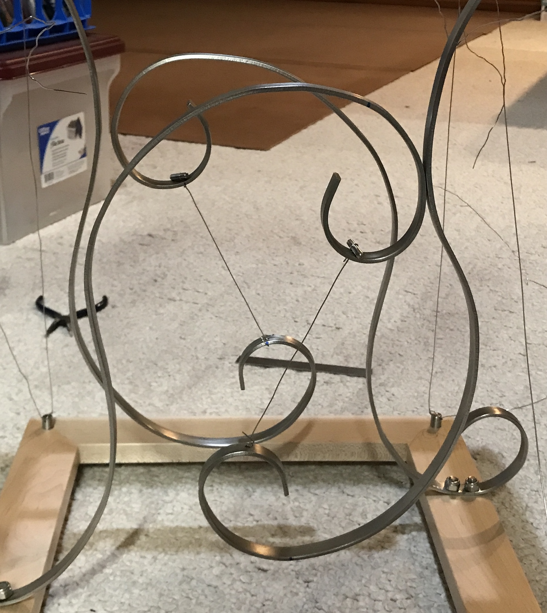
Before we move anything the table was partly rewired to better understand the problem. The wires running from corner to catty-corner were replaced with wires running from top to bottom. The first picture below shows the result of this effort. The shadow in the photo is most revealing. The table is reasonably sturdy, but has a pronounced twist. To remove the twist two cross-corner wires were reinstalled. These were placed to pull the table back into a proper orientation. As shown in the second photo this produced the desired result. The top shadow is square with the bottom. The S-curve supports are quite bent and one pair touches as seen in the third photo.
It has been three weeks since I gave this project any thought. My best guess is the problem arises because the stainless steel supports are too flexible. They need to be replaced with sturdier wooden supports. "Legs" are being considered. I like the idea: a four legged legless table.
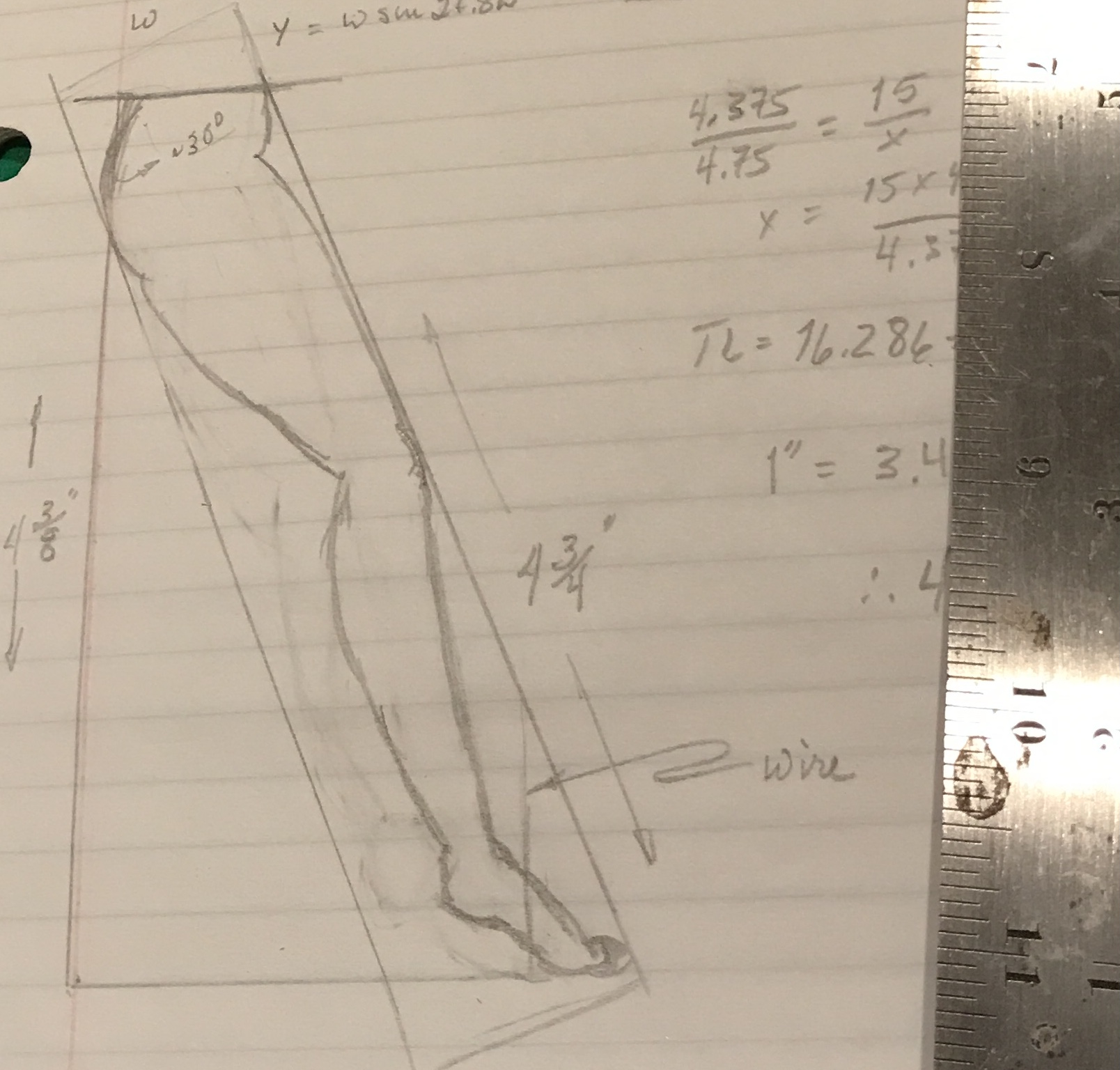
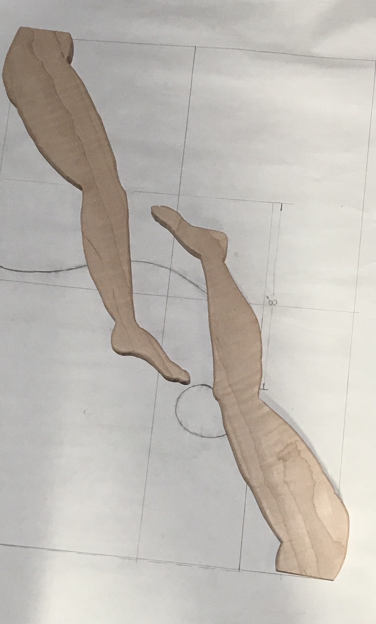
A little more sketching, measuring and calculating indicates a nice looking gam can be made from a 3 1/2" X 18 1/2" board. A 62" length of 3 1/2" maple was located as well as a 24" length of 4 5/8" walnut. My plan is to lay out the leg based on key points transfered from the drawing to the boards. Attaching the leg to the frame will take further consideration. The current plan is to cut a slot through the hip for nuts.
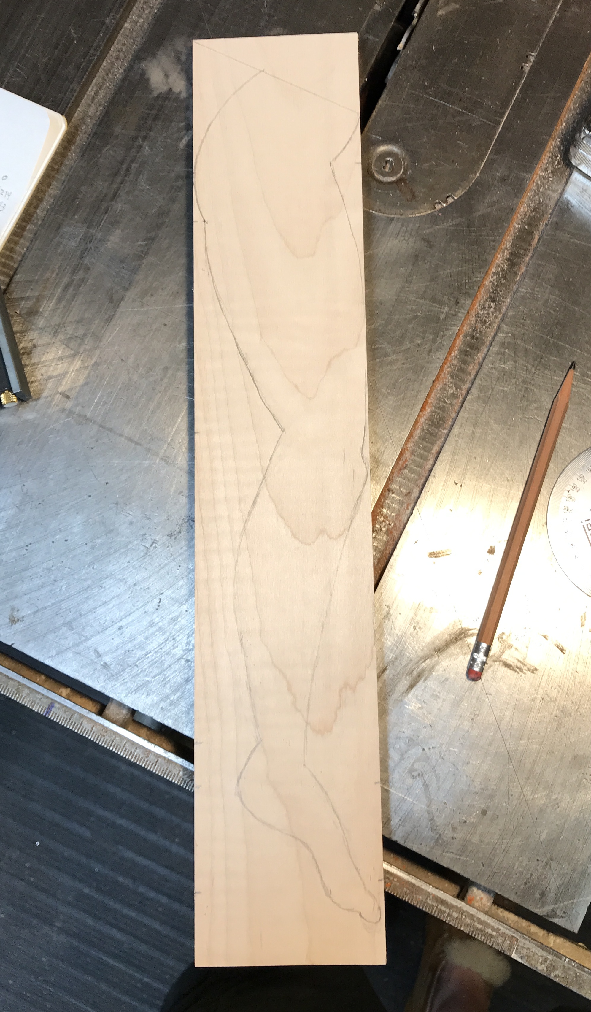
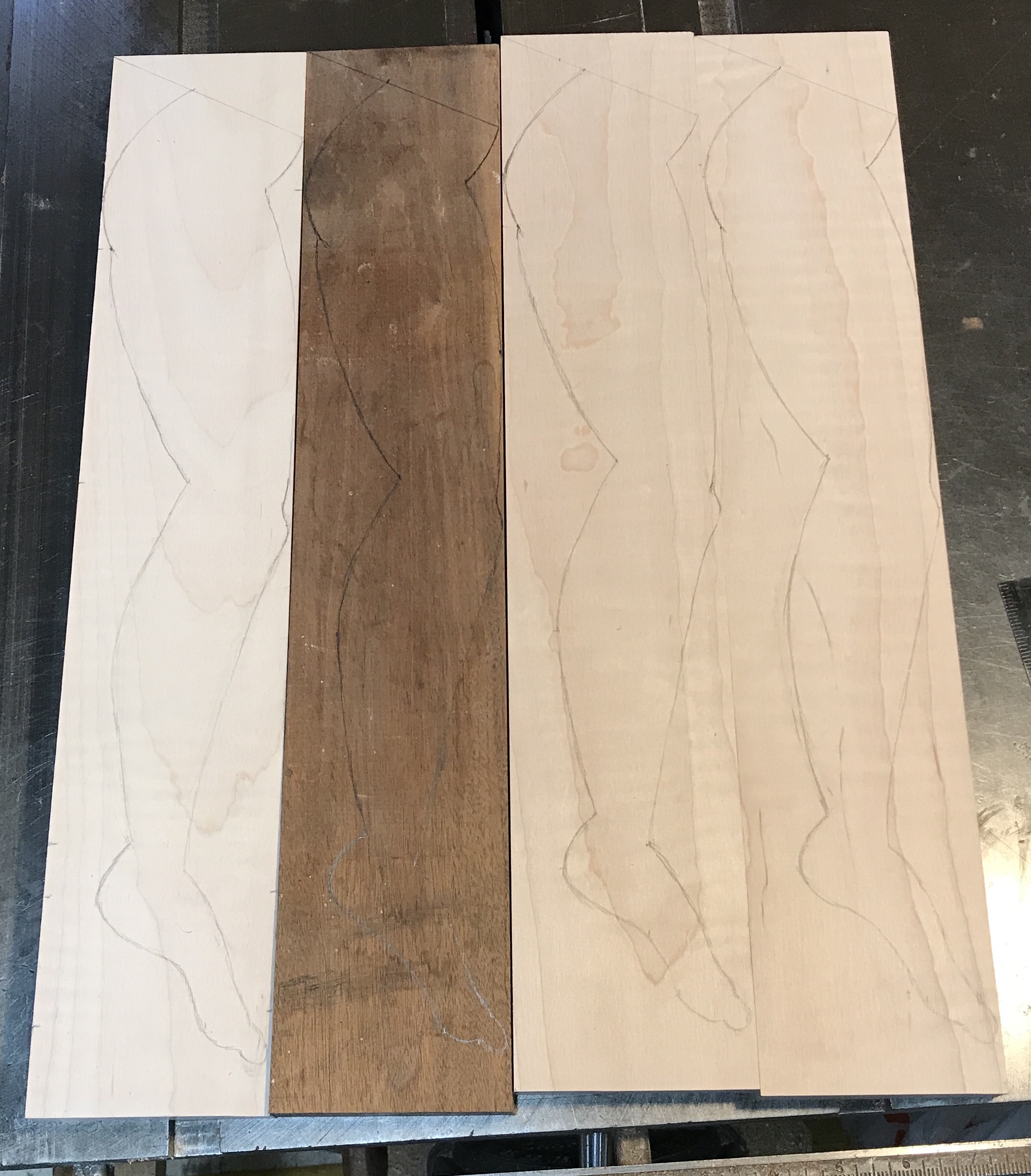
The walnut board was ripped to 3 1/2". All boards were then cut to 18 1/2" using the crosscut sled marked at the correct distance. After measuring key points on the plan, the dimensions were scaled and transfered to the first board. The dots were connected the the appropriate curves. Some adjustments were made. The key points from this first board were transfered to the other three boards and the curves added. The first photo shows the first gam. The second photo shows all four gams drawn and ready for cutting.
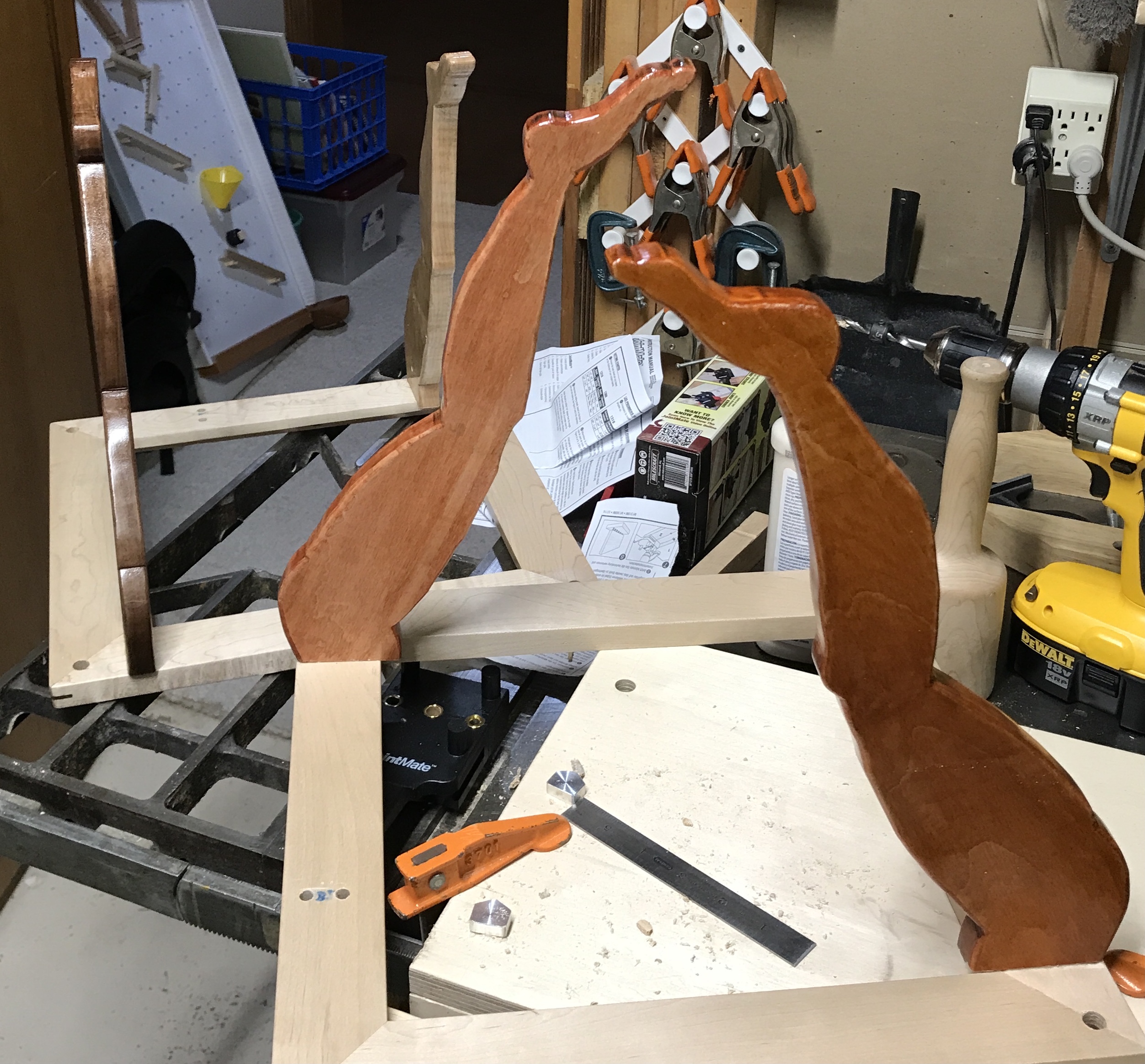
The unmarked side of the walnut blank had black paint on it and some very rough spots. It was sanded with the orbital sander using 120 grit paper. This was followed with 220 grit by hand. The jig saw was tried first to cut out the legs, but it just did not work. This was mostly an inability to holding the work rigidly. Cutting moved to the scroll saw. The first leg was cut out with a lot of difficulty. When cutting was completed, the blade was changed for a new one. The second leg (also in maple) was cut much more quickly with significantly less chatter. The photo shows the two rough cut legs.
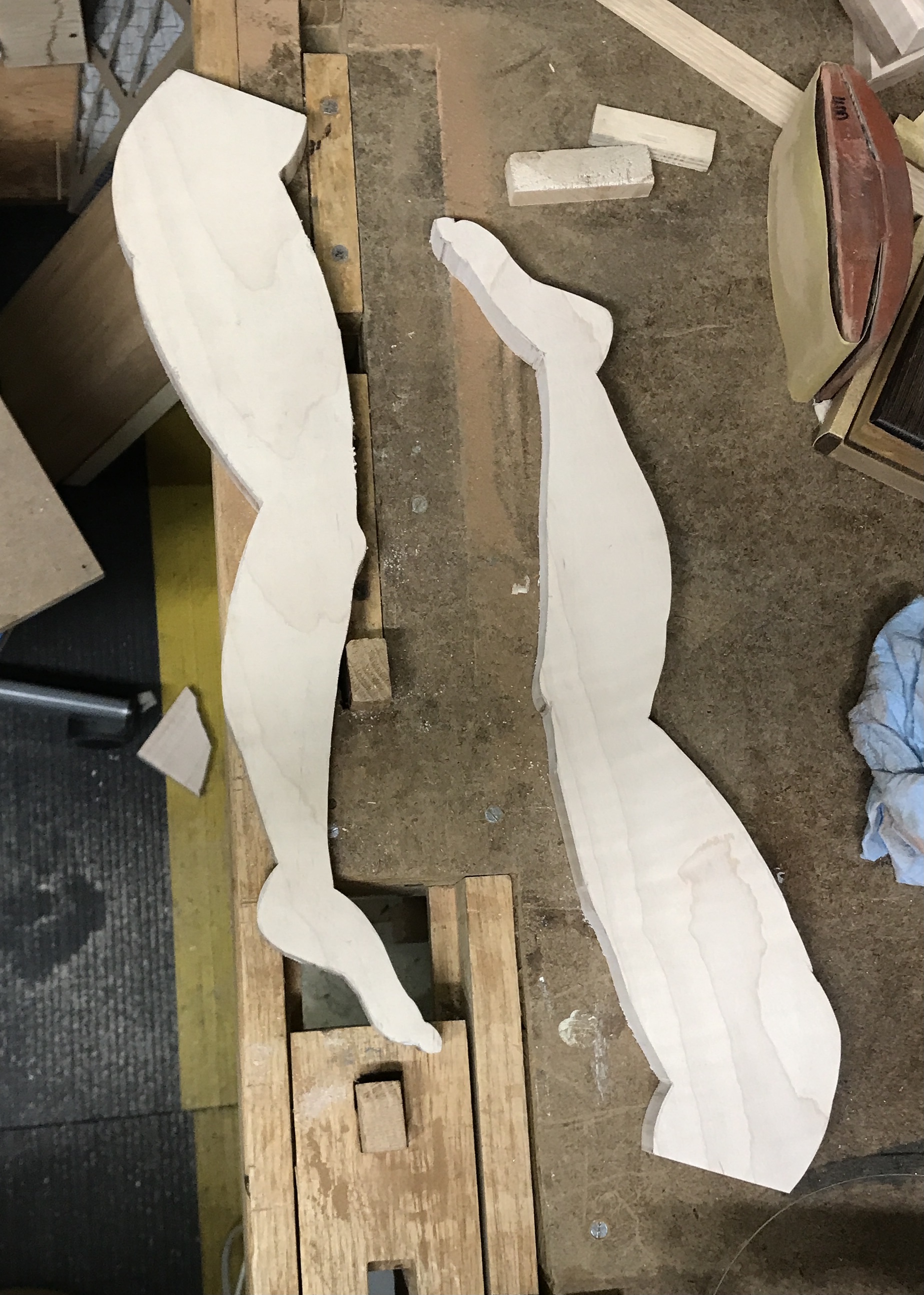
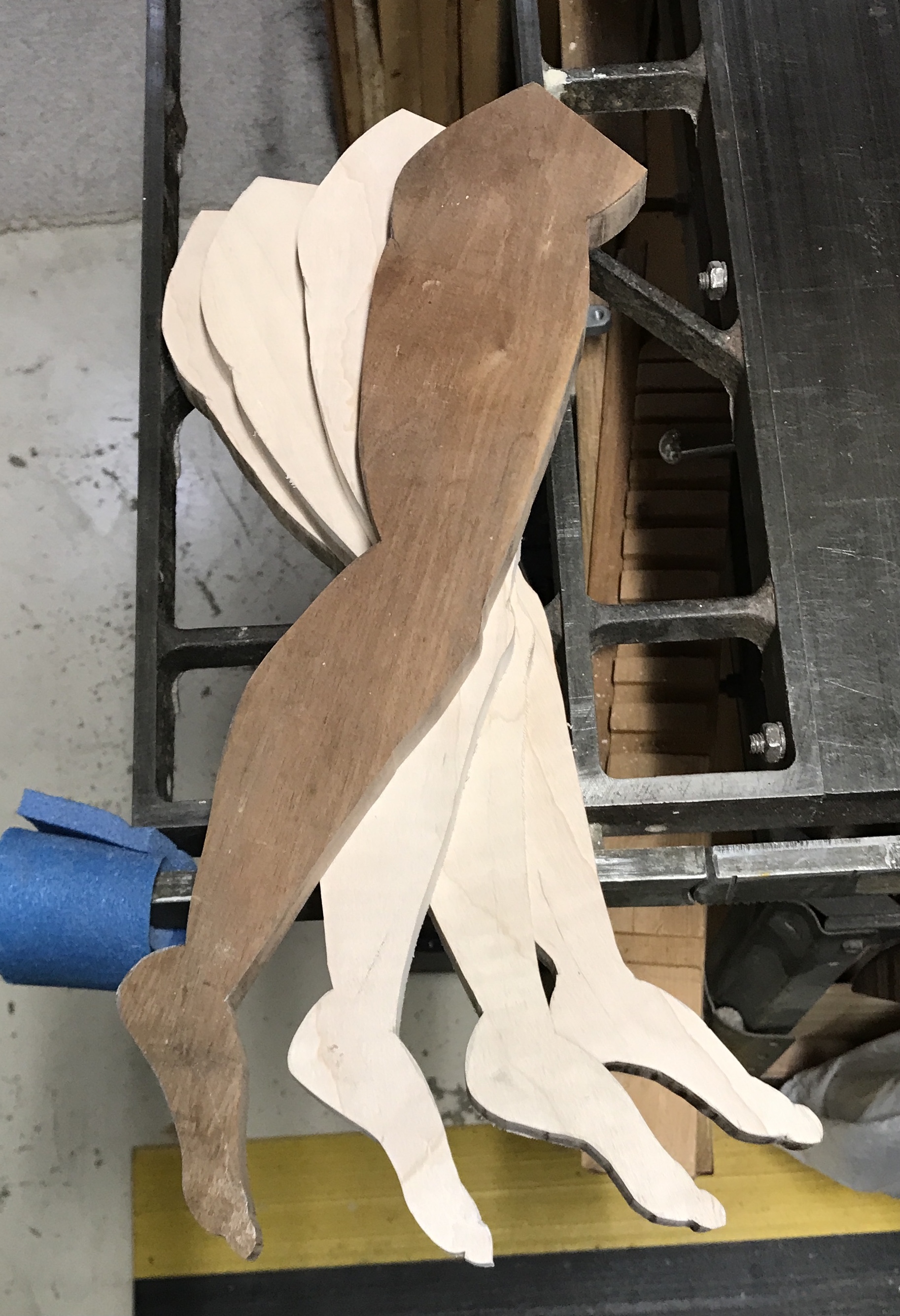
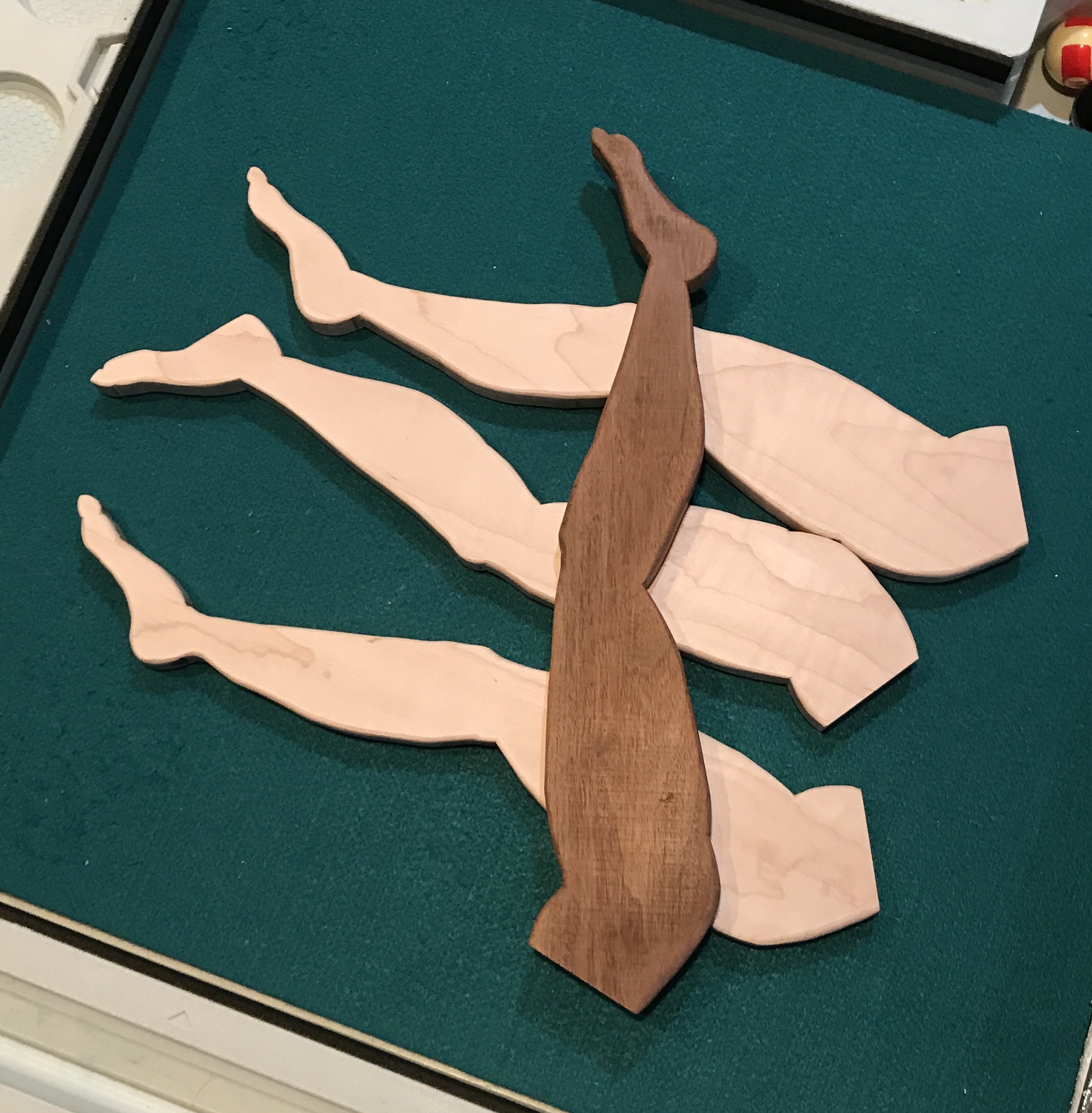
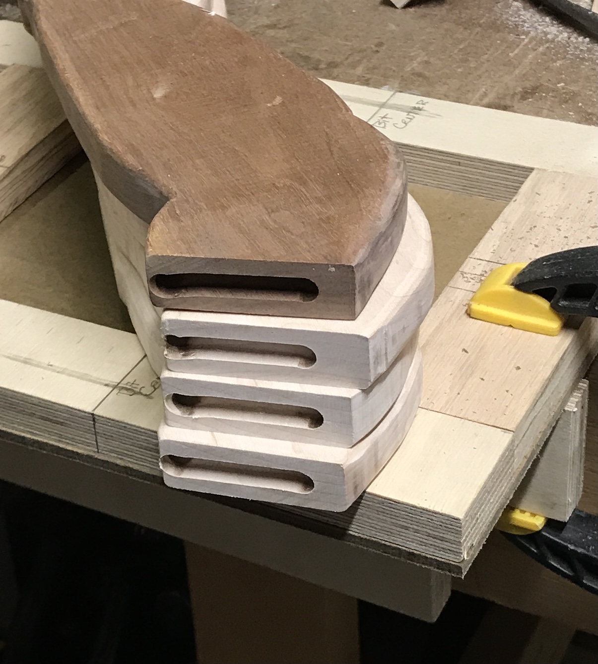
Glad that is over. The third leg was just as difficult as the second even with a new blade. The walnut leg cut like butter. Maple is hard and 3/4" is probably just too much for my scroll saw. All four are shown in the Rockettes photo below.
I followed Christopher Schwarz's instructions for sharpening a scraper using my scraper sharpening jig. First, the edge is filed flat and the edge is further flattened on a stone. Second, the faces near the edges are stoned using the "ruler trick". Third, the faces are burnished. Fourth, the burr is put on using the jig and a drop of oil. This gave a very uniform tiny burr, that would barely catch the fingernail.
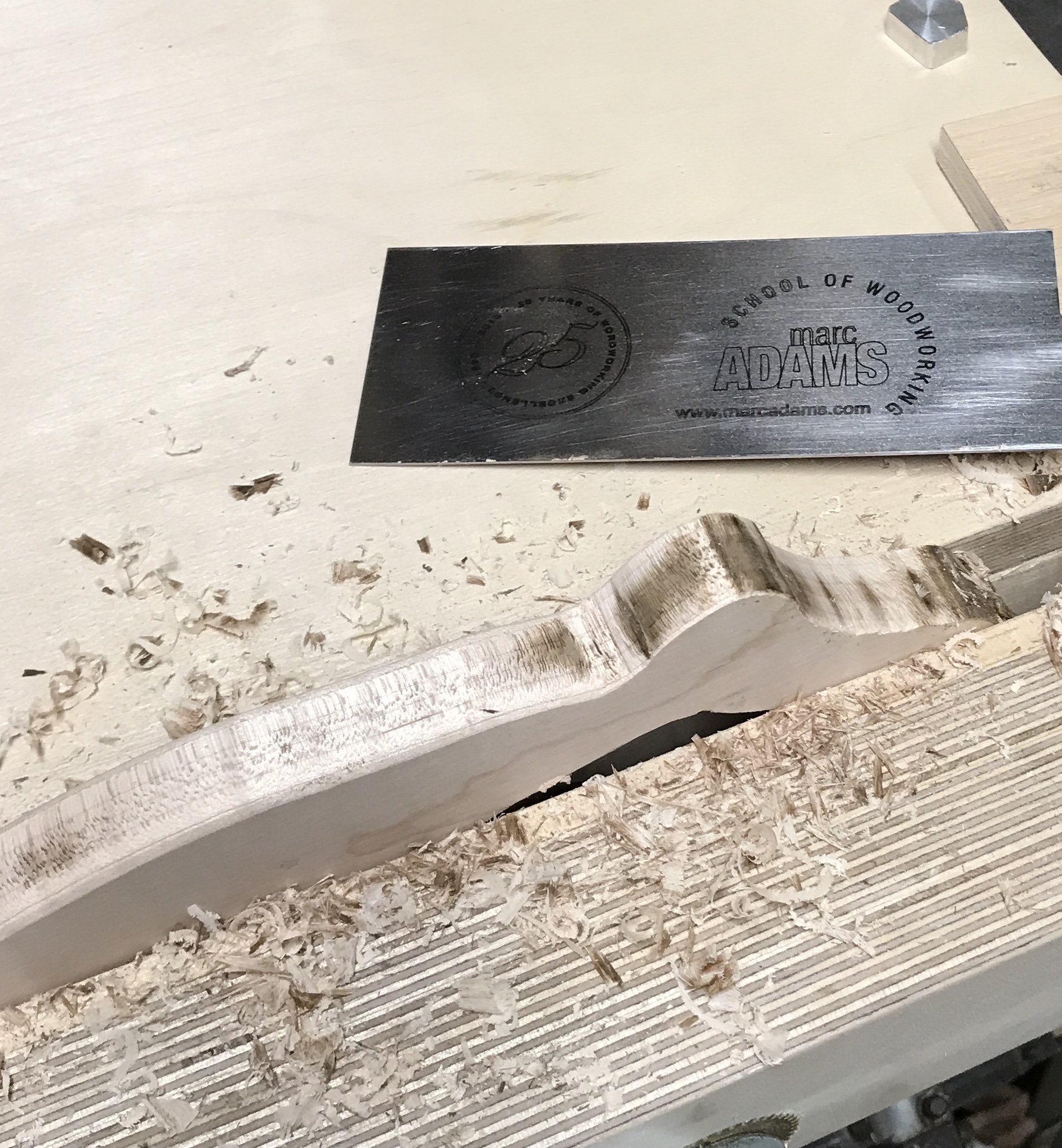
The first leg was held in the homemade Sjöberg vise, which was clamped to the table saw table. The scraper was used to scrape the sides of the leg smooth and to round the corners. Most of the burn marks were removed, but it was not possible in my lifetime to remove all traces of them. The direction of scraping depended on many factors and varied across the length of the leg. It was always trial and error. The corners were most prone to tearout if the scraper was used in the wrong direction. There are three photos of the first leg: working on the foot end, the finished hip end, and the finished leg.
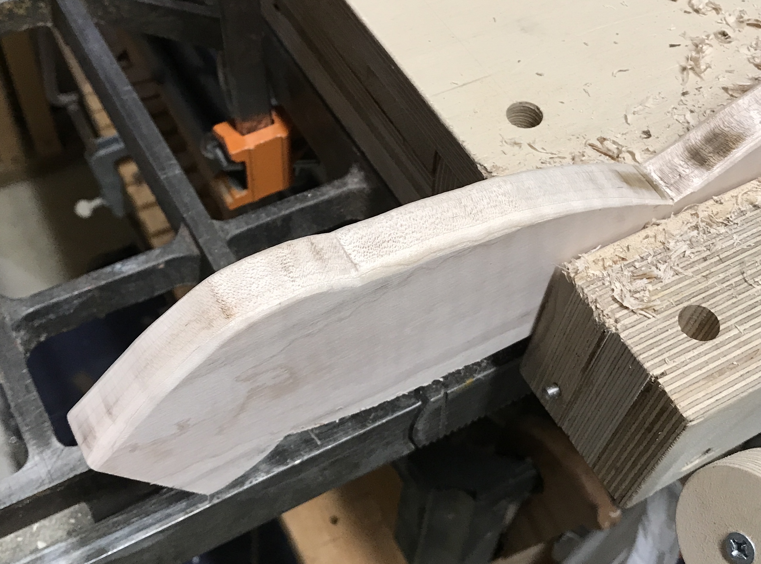
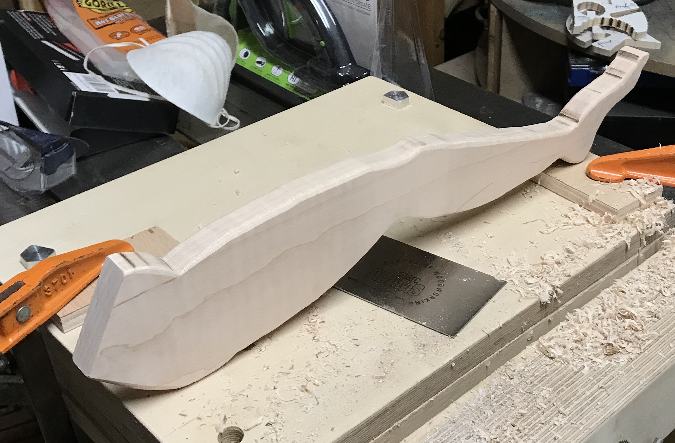
After two maple legs the burr had to be redone. Similar to the scroll saw, the walnut leg, cut last, was the easiest to cut with the scraper. The walnut was more prone to tearout on the corners. All four completely scraped legs are seen in the next photo. Some sanding is needed in spots, especially where the change in direction is particularly abrupt.
Sanded the legs all over with 320 grit sand paper. The tighter spots were sanded with small sandpaper covered rods and sticks. The legs need to be laid out and nut slots cut. The current square headed screws may not be long enough. They extend about 5/8" beyond the frame. If the slot is cut 1/4" from the top of the leg, they might just fit. I worry about the wood splitting once it is under tension. It probably makes sense to use some sort of washer that extends the full width and length of the slot to spread the stress over more wood. 2" long stainless steel screws were ordered.
The long screws provide more flexibility for the location of the nut slot. A slot that is 1/2" below the top of the leg should provide the required strength. The screw separation is already set at 3/4". Room also needs to be left to get a wrench around the nut. The legs are approximately 2 1/4" wide. A 1 1/2" long slot should be sufficient for the screws. The slot should be a minimum 3/8" wide. The best way to make this slot is not completely clear. The mill could be used, though clamping the leg may be difficult. Tearout is also a problem with the mill. The router would be the first choice of a true woodworker. A jig for controlling the location or a set of stops on the router table would be required.
Spent about two hours getting the router table set up with two stops that had to be made. Carefully examining the table and the screw locations convinced me that the slot idea won't work. The screws are too close to the outer edge. The slot would need to be very close to the butt side of the leg.
I am now considering a spline. A dado would be cut in the table at the location of choice. A matching dado would be cut on the waist of the leg. Glue and a spline would hold the parts together. The dado could be stopped so it is not visible from the outside of the table. Clamping during glue-up can be done by clamping the leg vertically and putting weight on the frame. Angle brackets along the sides are another possibility. The torque is down and out at the joint. The spline should be sufficient for a solid attachment.
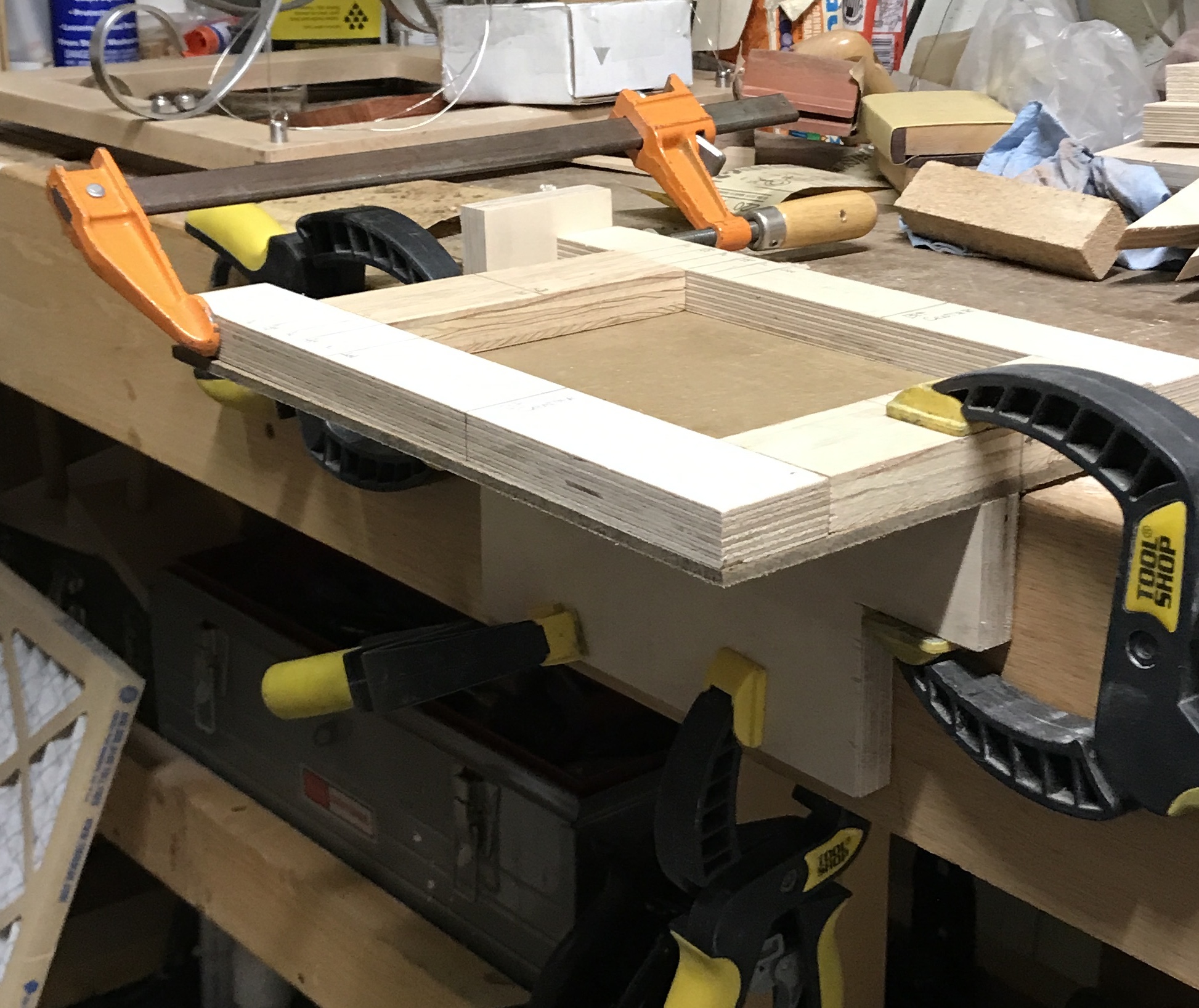
The morning was spent making the jig for slotting the legs. It is essentially a U shape of three boards screwed to a 1/4" hardboard backing. The fourth leg of the final rectangle floats between the two long arms of the U. The long sides are 13" long and the two short sides fitting between the long sides are each 6" long, which is the diameter of the small router base. The base is 9" X 13". The three sides of the U were drilled and screwed to the base with 5/8" long #8 wood screws. Four screws are on one long side with only two on the other so the end floats a bit. The first photo shows the jig assembled with the movable side clamped. The second shows the vertical clamp used to support the jig and clamp the leg below.
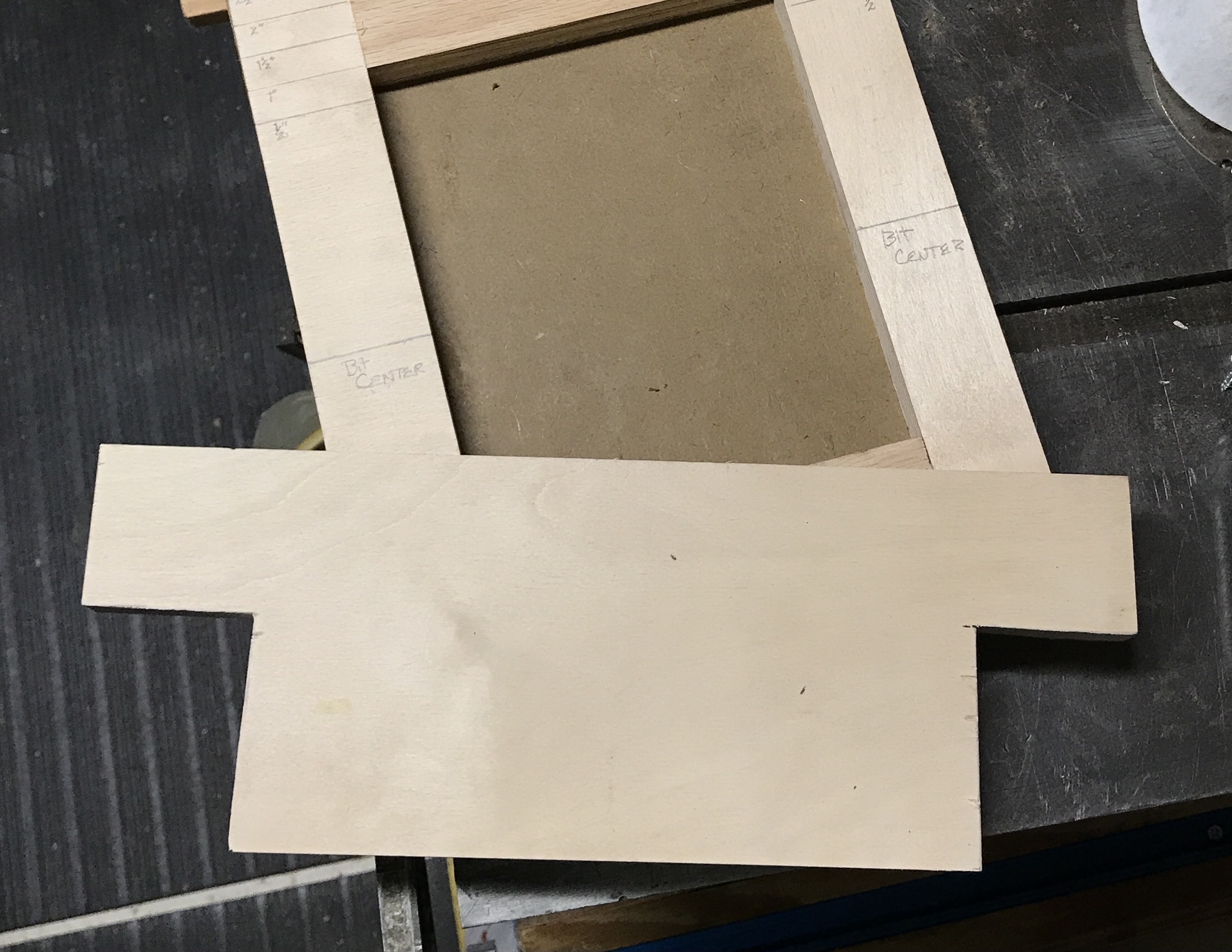
Multiple marks were made on the jig. Some show the center of the router bit, while others show where to place the movable stop for different length slots. The second photo above shows some of these marks. The photo below shows the jig clamped for use. (A lot of clamps, but no work piece!)
The jig was tried out just using the vertical clamp with nothing inserted. The first pass at 1/4" depth made the slot in the base plate. The second pass at 3/8" cut a slot in the clamp. The slot is not centered. It is closer to the table side as clamped. Either I did not line up the table marks correctly with the edge of the table or the clamp was cocked at a slight angle. The next trial will be with scrap stock.
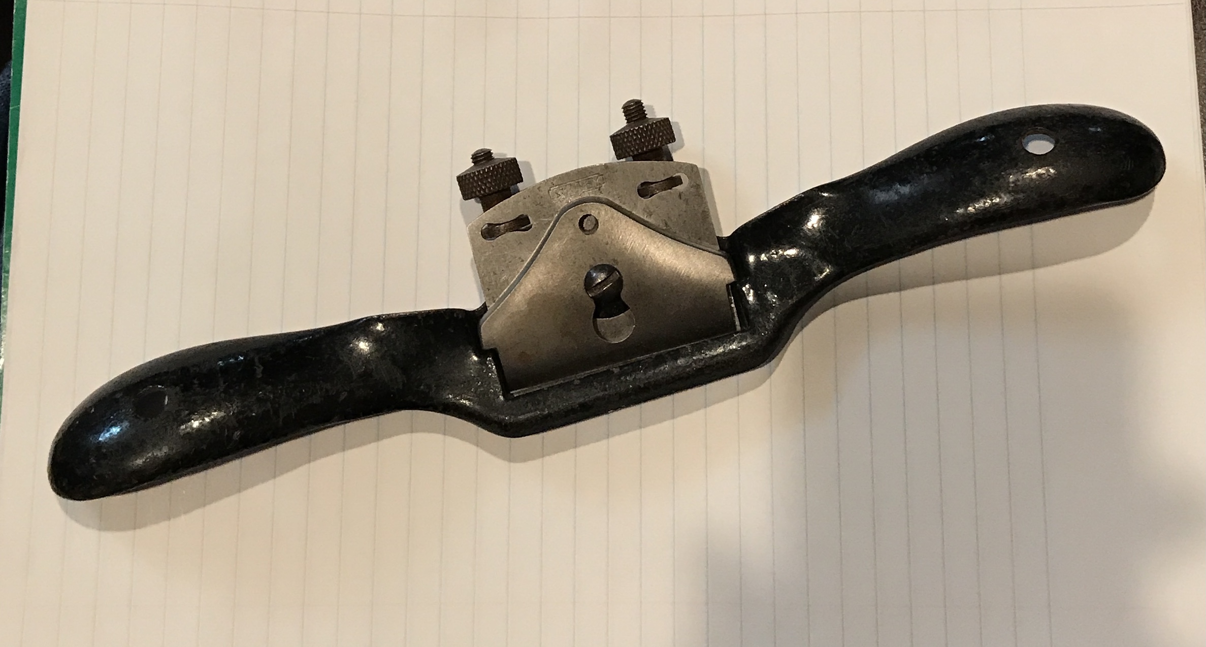
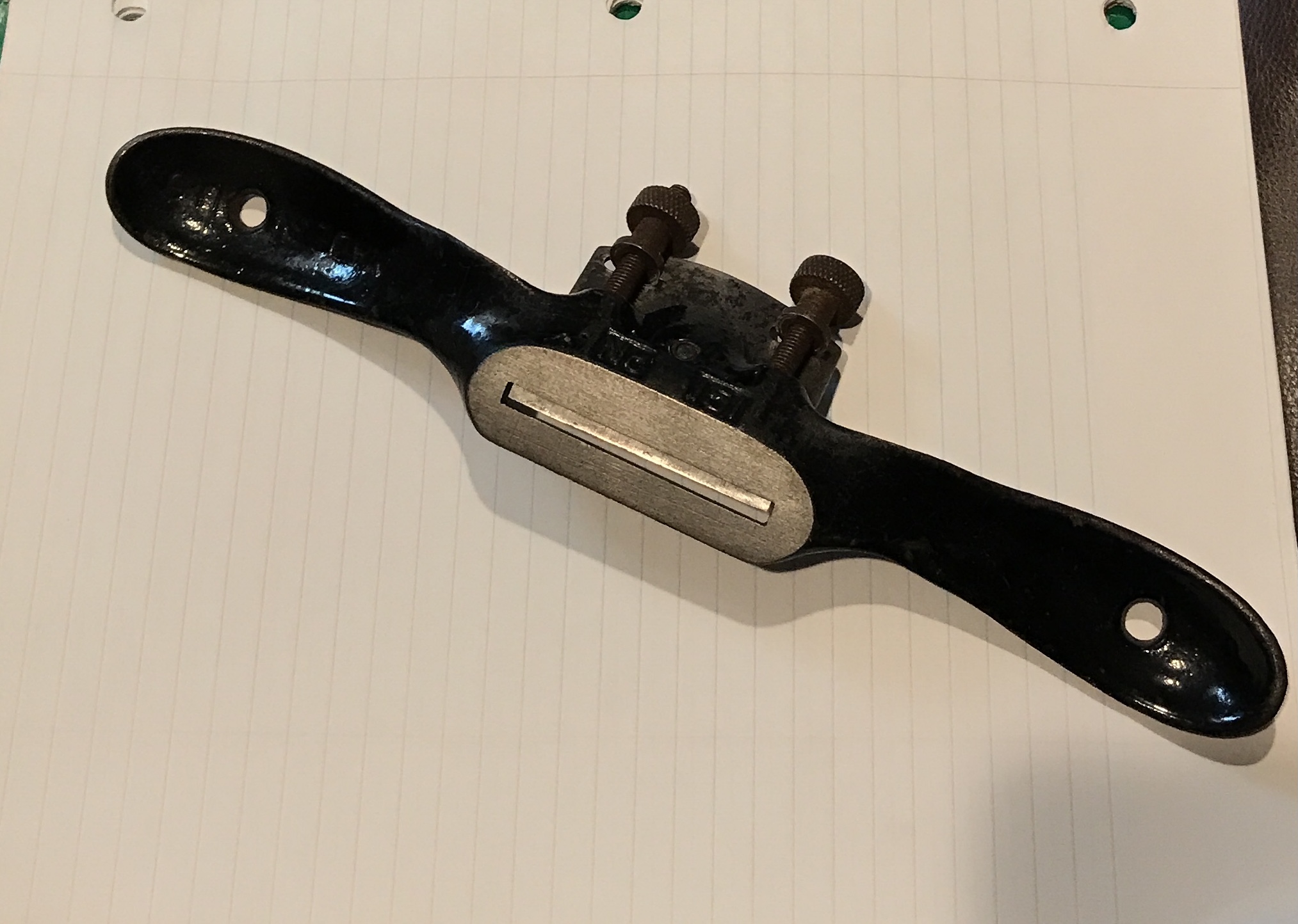
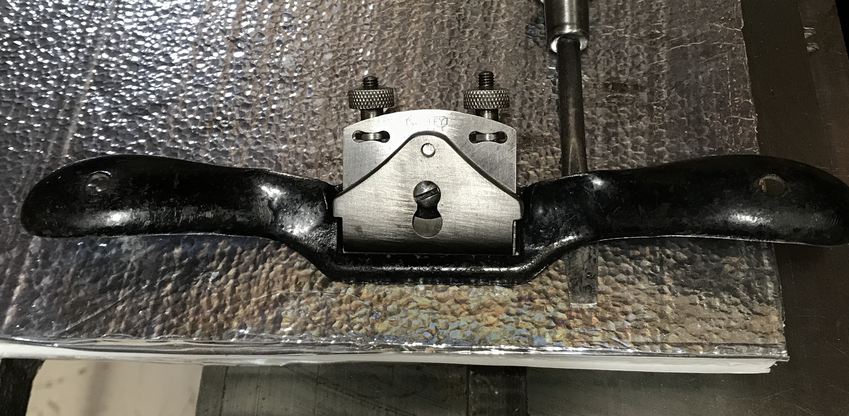
I purchased a Stanley 151 spokeshave from eBay to shape the legs. It just arrived. Too late for the legs. I will need to think of another use. It needs a bit of rust removal and the blade needs to be rounded and sharpened. A few days later the rust was removed with the Scotch wheel. The derusted spokeshave is shown in the third photo.
The jig was adjusted until it was centered on 3/4" scrap stock. The first leg was clamped in place. Clamp adjustment along with an extra clamp were needed so the leg was held tightly. The cut was made in this leg and the next three legs. All of the dadoes are centered. The only bothersome thing is a slight jog at the beginning of each cut. This is lessened on the cuts that were at the edge of the leg. It would have been avoided it the cut started outside of the leg.
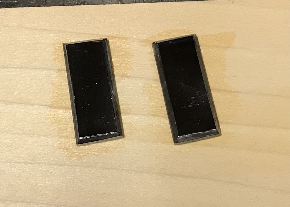
The table frames were dadoed on the router table. The fence was set to the distance from the outside of the frame. A stop was set so the cuts are 1 1/2" long. The 1/4" bit was set at 1/4" depth of cut. All four slots were cut in the frame after carefully considering where they needed to be located. There was significant tearout upon router bit entry. This was only right in the corner, so it should be well hidden. The cuts were cleaned up with sandpaper. This included removing finish around the dado, so the glue will stick.
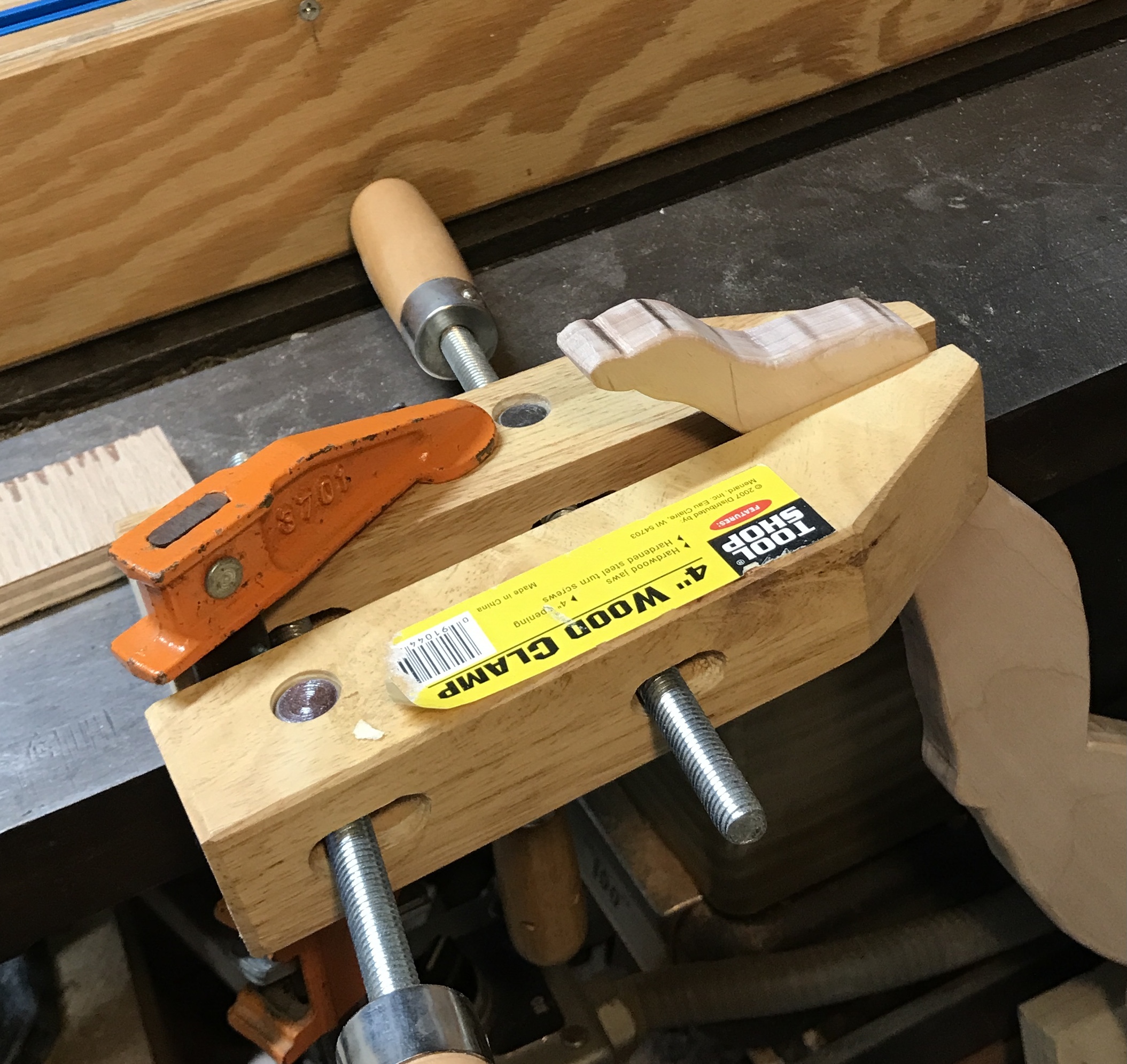
The legs need to be finished and drilled prior to assembly. The legs were laid out on the pattern used earlier to mark the S-curves. In order for the feet to overlap correctly the legs will need some 1/8" thick wedges (7°) to modify their angle relative to the frame. The first photo shows ideal alignment. The second shows the slight angle required. The feet were marked for drilling while checking this alignment.
The legs were clamped in a large wood clamp. The clamp was held to the table saw table with a bar clamp. The line on the foot was aligned with the vertical and the hole drilled with a #50 (0.070") drill.
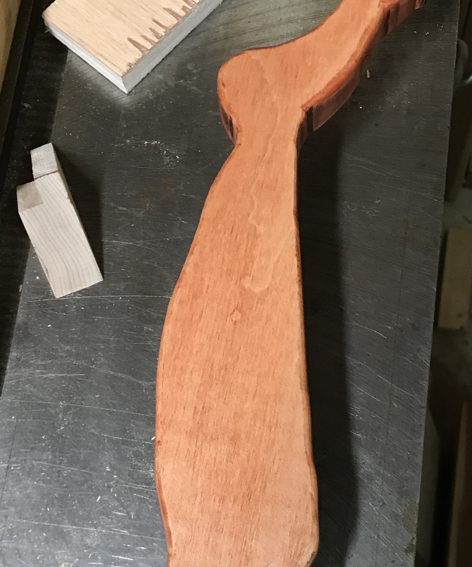
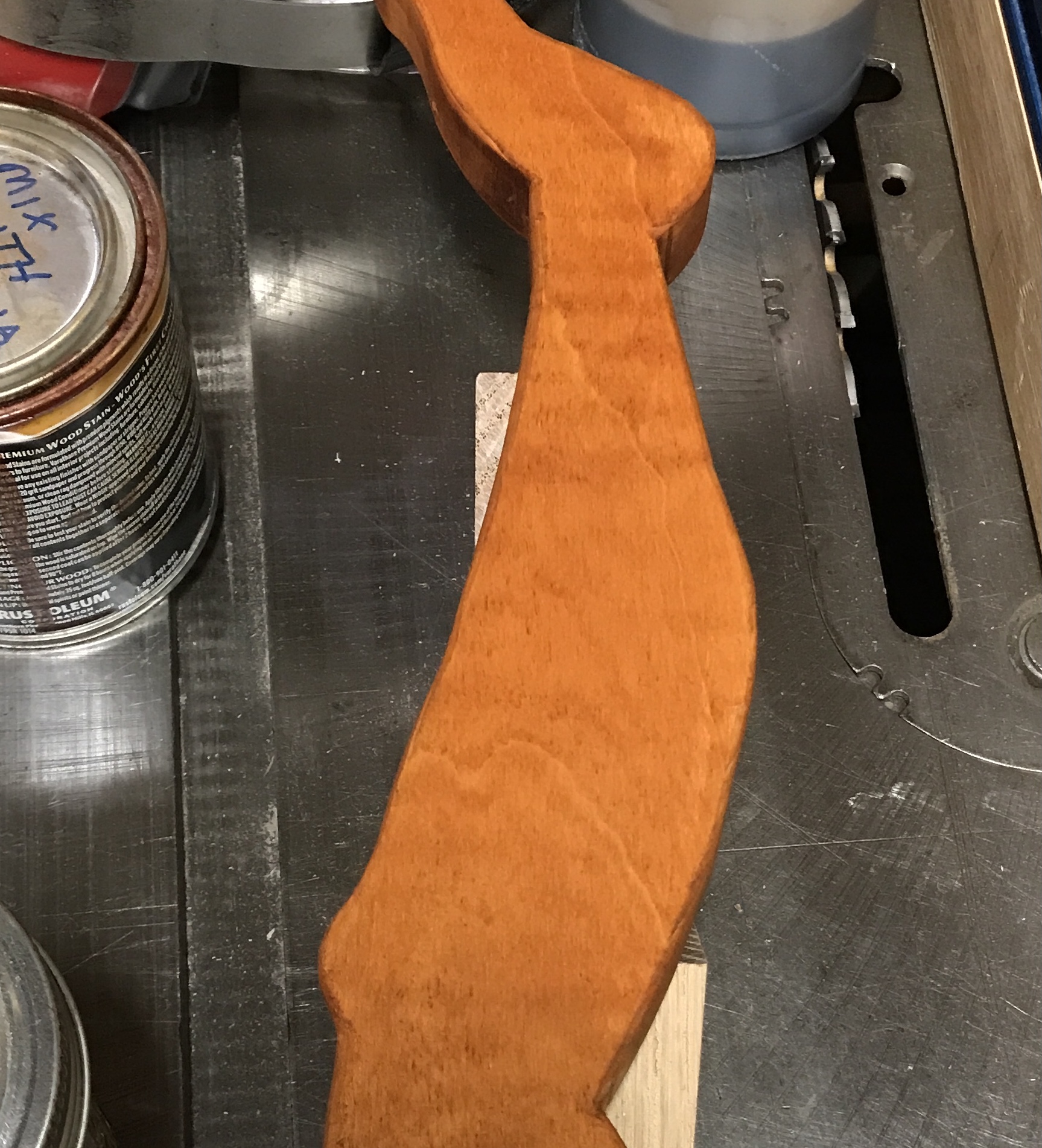
After playing with stains a bit I decided on the reddish mix used on the wedding backdrop and an oranger version of the stain used on the G&G table. One maple leg was stained with each color and the excess wiped off after a few minutes. The photos show the two, but not true, colors.
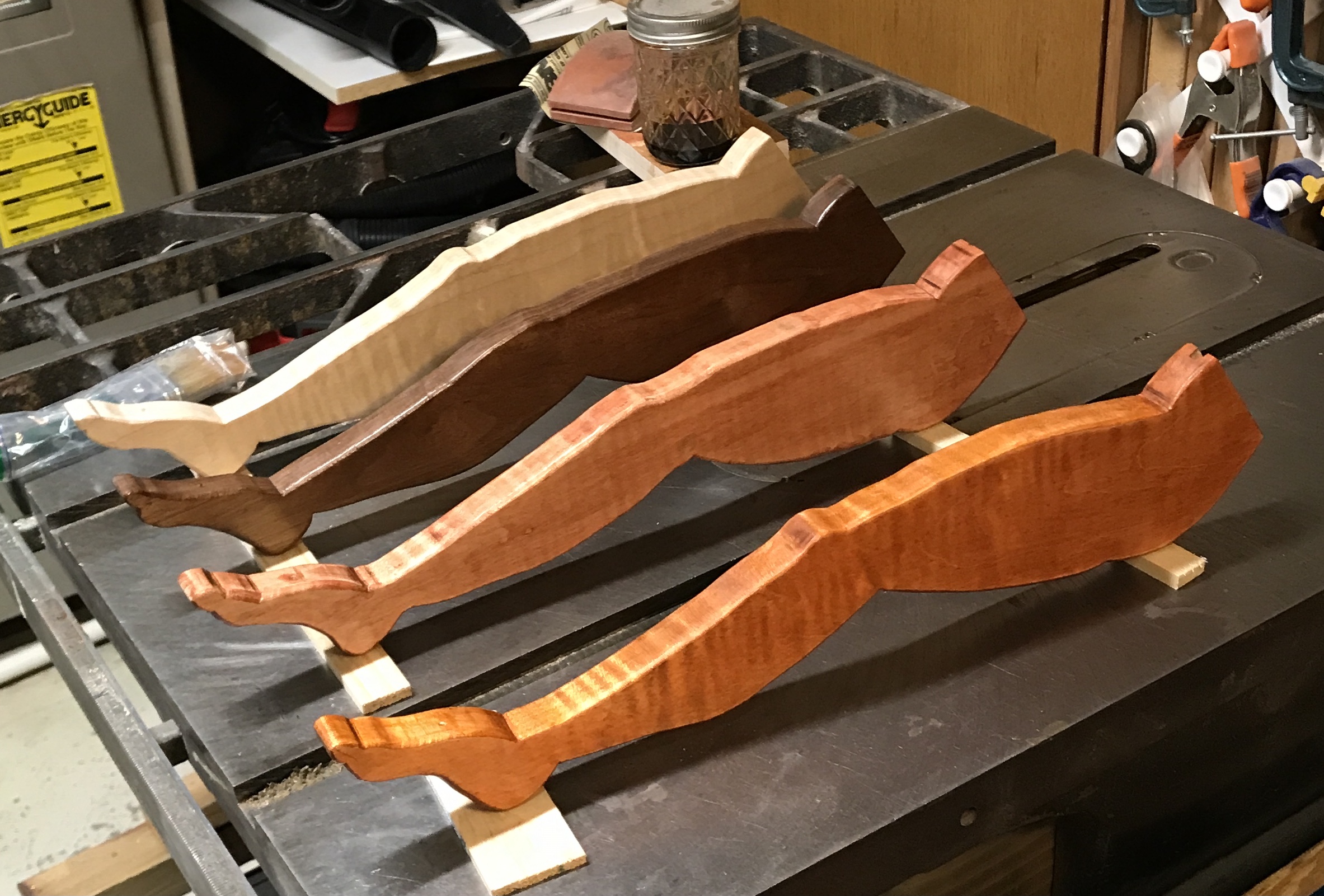
The final finish on the legs is shellac. It dries fast between coats and goes on easily with a brush. At eight o'clock the four legs got their first coat of shellac as seen in the following picture. Two more coats over the span of the morning finished the legs.
Four small wedges were made. The miter gauge was set at 7°. This was done using the Pythagorean Triples calculator. The triple [147,1196,1205] was chosen. As measured with the framing square The short leg was set at 1 15/32" and the long leg at 11 31/32". A scrap of Baltic birch plywood had the corners cut off. After losing one of the wedges through into the sawdust the zero-clearance insert was used. Cutting off the sides after using all four corners provided another source of wedges. The wedges were 1/8" at the high side.
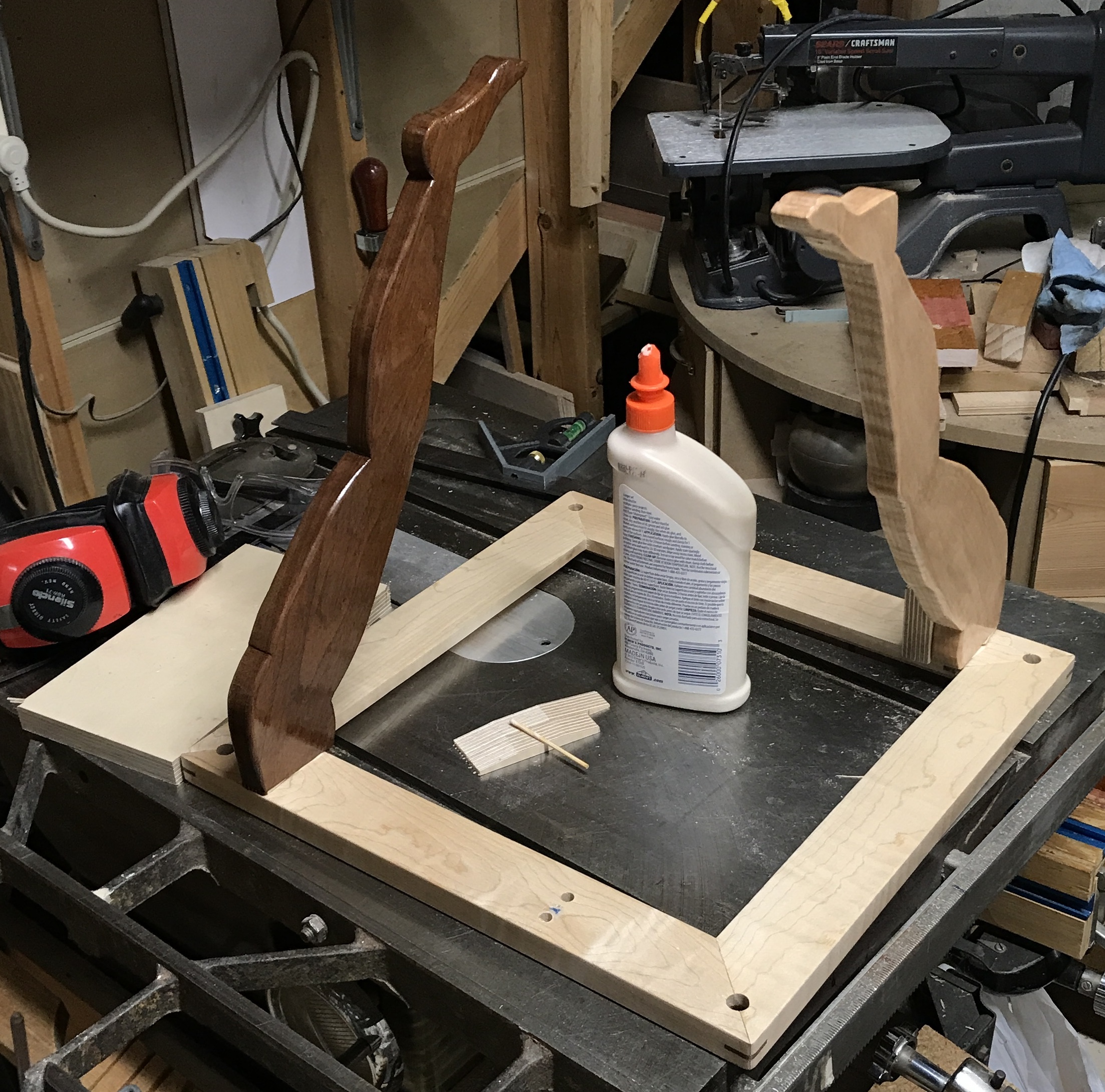
A cutout was made in a wedge. This first wedge was for the walnut leg, so some dark stain was applied to the visible edge. Glue was put in the slots in the leg and table top. More glue was put around the slot. The wedge was put in place along with the spline. The leg was pressed into place. This spline fit tightly, so there was no need to hold it in place. The unstained leg was glued next. The spline was looser for this leg, so it was necessary to hold it for some time. I could not think of a way to clamp it. A small block of wood was used to ensure orthogonality to the frame. The photo shows the two legs with glue drying, attached to the underside of the top frame.
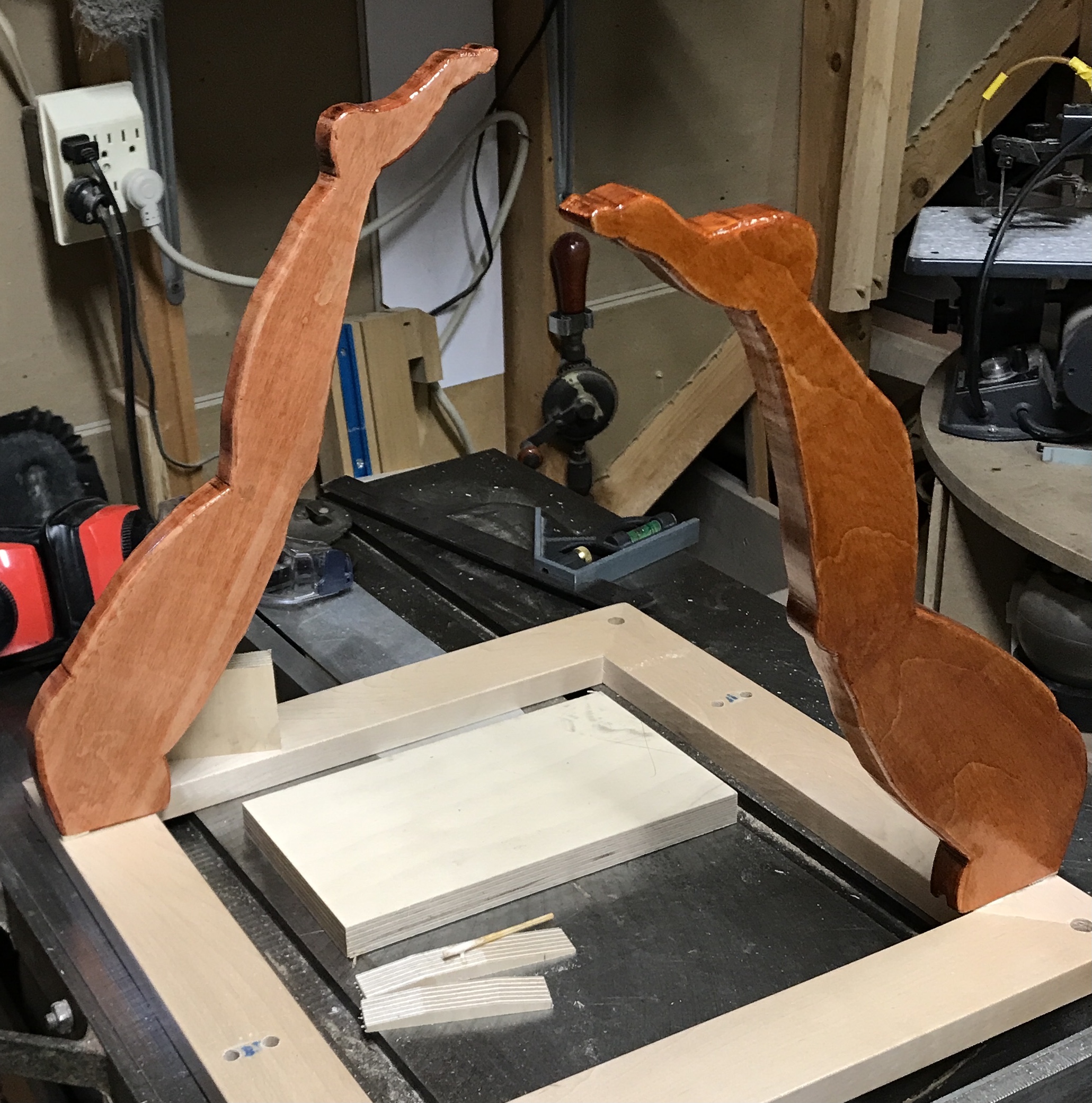
The same activities were conducted to attach the last two, red and orange legs, to the topside of the bottom frame. The joints were serviceable, but there was little contact except for the spline. The wedges were not as effective as hoped. The picture shows the result. After the glue had dried the legs were checked for alignment across frames. That is the top frame was held above the bottom frame. The legs wanted to occupy the same space!
After sleeping on it the problem became obvious. The wedges were put on the wrong side! Instead of fixing the overlap with a 7° angle, the problem had been compounded! The solution was also obvious. The legs were cut off with the FatMax saw. This worked nicely leaving no trace of saw marks on the frame. The sawing went very quickly because the joints were so poor.
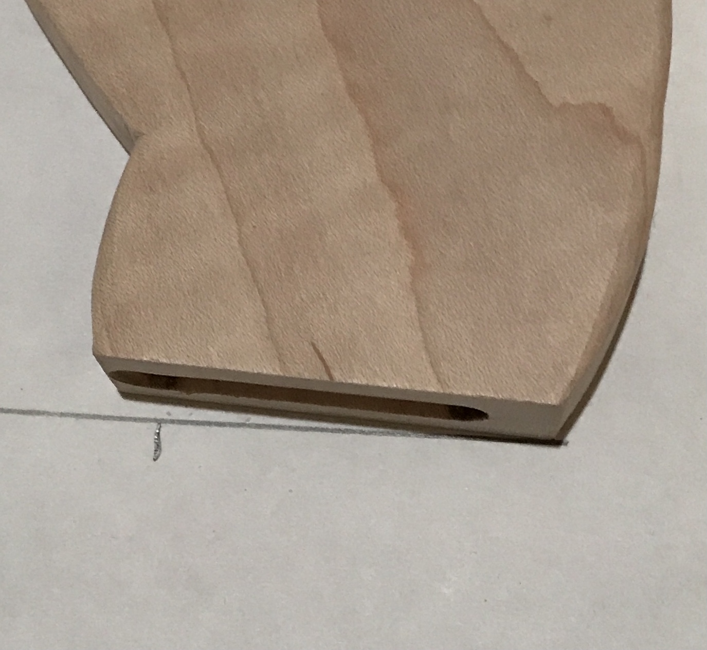
Wedges were not effective so the legs needed to be fixed instead. The dado with the glued spline also needed to be removed so the parts could be attached with dowel pins. A leg was positioned on the crosscut sled, such that 1/4" was to be cut off on the inside and 3/8" would be removed on the outside (butt side) of the leg. A quick cut and the leg is shorter and now has the proper angle. This was repeated on the other three legs. Thirty minutes after starting the FatMax sawing the legs were ready for reinstallation.
The legs will be attached with dowel pins. The appropriate pin size for 3/4" stock is 5/16". There are only four 5/16" pins in the box. I will purchase more this morning. After the trip to Home Depot the Joint Mate was used to drill holes in the legs and matching holes in the frame. There was some consternation gluing the first leg in place. The holes in the frame were supposed to be 1/2" deep, but were only 3/8". Once this was discovered the offending pins were shortened and the joint was glued. The second leg went much smoother after drilling the holes in the legs a bit deeper. This is harder than expected mostly because these are not regular squared up boards.
The final two legs were joined this afternoon. The picture below shows the two frames with attached legs. Some clean up will be needed before wiring them together. Some plugs also need to made for the bolt holes in the bottom frame. Alternatively, square headed screws can be fitted, though there is a blue mark between them that was covered by the S's.
Upon looking over the legs and frames, I found a few areas on the legs that were scuffed up. A trial run with paste wax seemed to be sufficient. The legs and frames were all coated with paste wax. After drying the finish was buffed with a soft cloth.
Two rectangles of steel need to be made to hide the holes in the bottom frame and the space between. They will be 1/2" wide and 1 1/4" long with a heavy chamfer. Not sure how to glue them in place, maybe hot glue. A piece of 1/8" hot rolled steel was cut to 2 1/2". The belt sander was used to get rid of the scale. The sides were sanded with 120, 220, 320, and 400 grit sandpaper. The chamfers on the long sides were cut on the mill with the head set at 45°. They are 0.030" deep. Two parts were cut from the steel, both 1 1/4" long. The ends of the these parts were then chamfered. Both parts were polished using green rouge on the polishing wheel. After cleaning the parts were painted with Protecta-Clear. They look black in the photo, but they really have a nice shine.
My adhesives chart recommends either super glue (cyanoacrylate) or two component epoxy for joining wood and metal. The superglue might color the wood, so epoxy will be used.
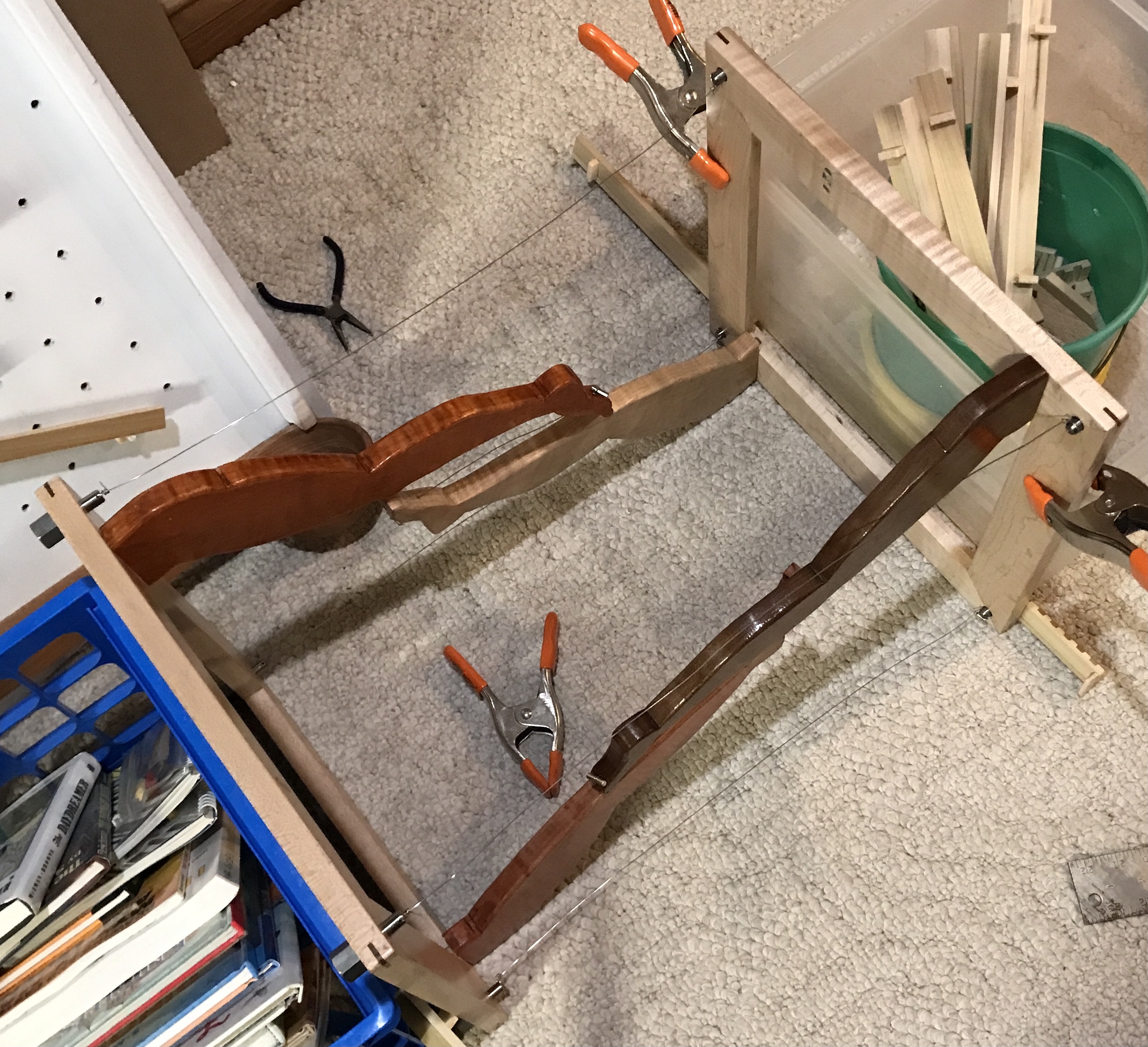
It was time to put it together. Before that could be done two more pins were made for holding the wire between the feet. The stainless steel rod could not be located, so two pins were made from brass, 3/16 X 5/8". The ends were heavily chamfered and the brass was polished with crocus cloth. The two frames were clamped to crates and boxes as before, squared up and adjusted to 22". Wires were bent around the stainless steel pins, threaded through the holes and looped around the brass pins. Both feet were about 7" apart.
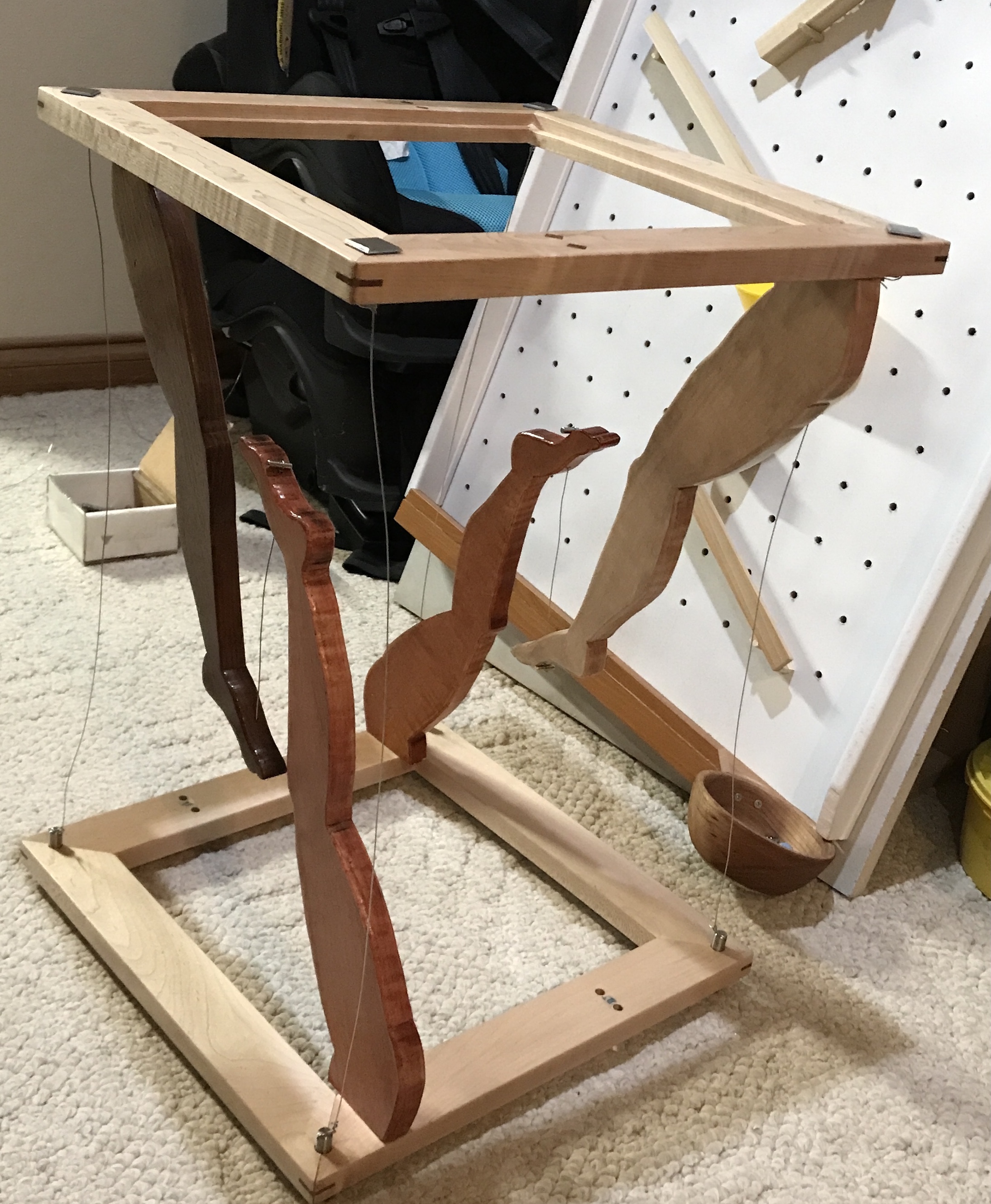
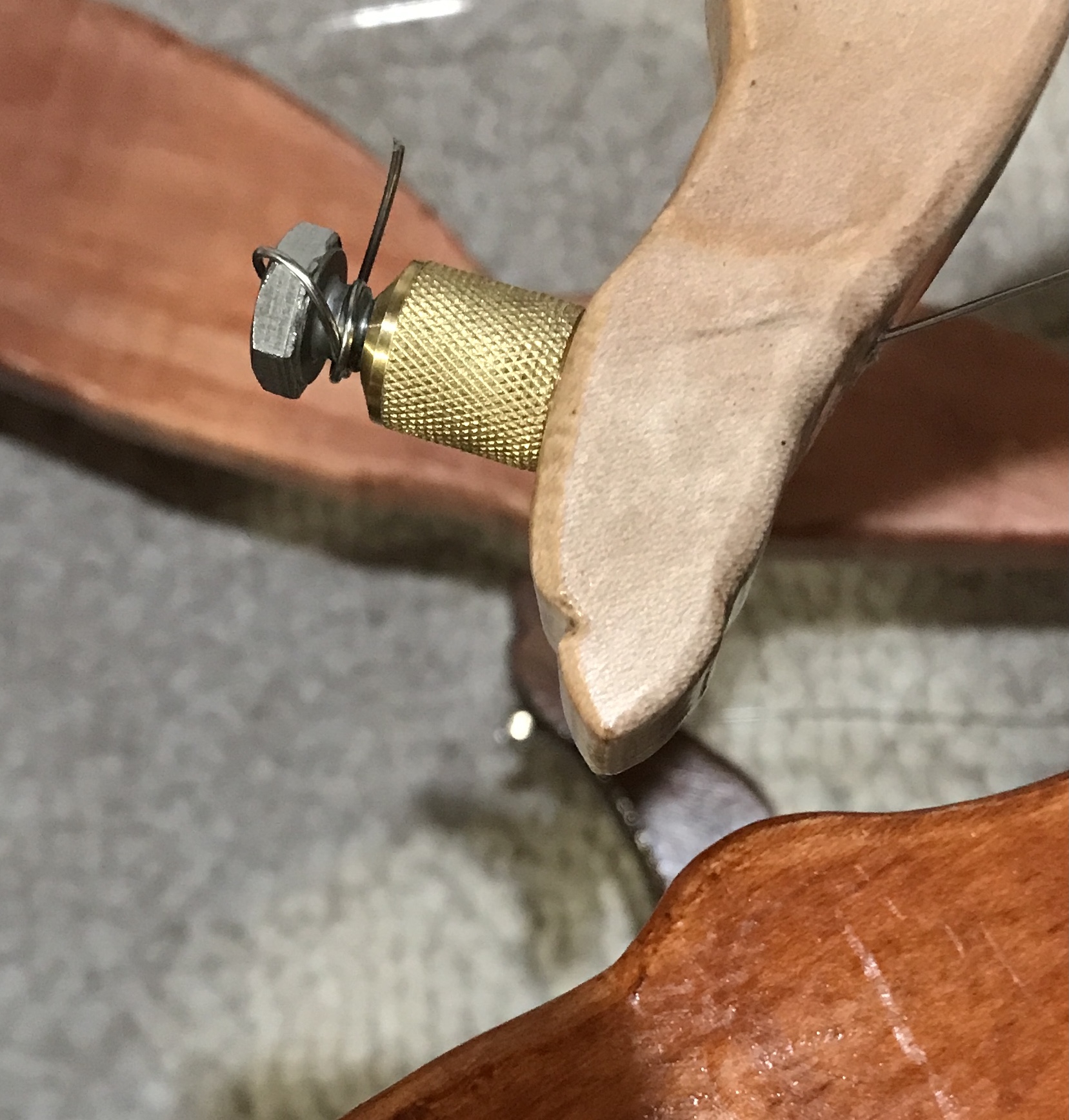
A cufflink was inserted in the top and a 24" long wire was threaded through the hole. The wire was wrapped around itself. The other end was threaded through the fully open adjuster, which had been inserted in the bottom frame. This was repeated at the other three corners. The first picture shows the clamping. The next two show the table at this stage after standing it up. It is twisted as expected. The adjusters were all tightened. This resulted in more sturdiness, but it still wants to twist. The last picture shows the table at with the adjusters tightened. The adjusters were completely tightened and the wires were still a little loose, so the wiring will need to be redone. The glass was inserted and the table had no problem holding it up.
It's the twist damnit! I still can't seem to get rid of the twist no matter what I do. I will give it one last shot. If the two wires between legs are not the same length this might lead to a twist. Another adjuster was made. A scrap of knurled 1/2" brass was faced and drilled with a #7 drill. It was tapped 1/4-20. One of the drilled screws from above was shortened. This was put in place as shown in the photo below. Even when tightened it had no discernable effect on the twist.
At this point there is no more room for adjusting the four corners. They were all rewired to provide some play. When tightened there is still twist. The square headed screws made above as well as the recently made plates were epoxied in place. When the glass was installed two of the wires went slack and had to be rewired yet again. Well it ain't pretty, but it will have to do. The last photo shows the completed, twisted, legless table. I do like the legs!
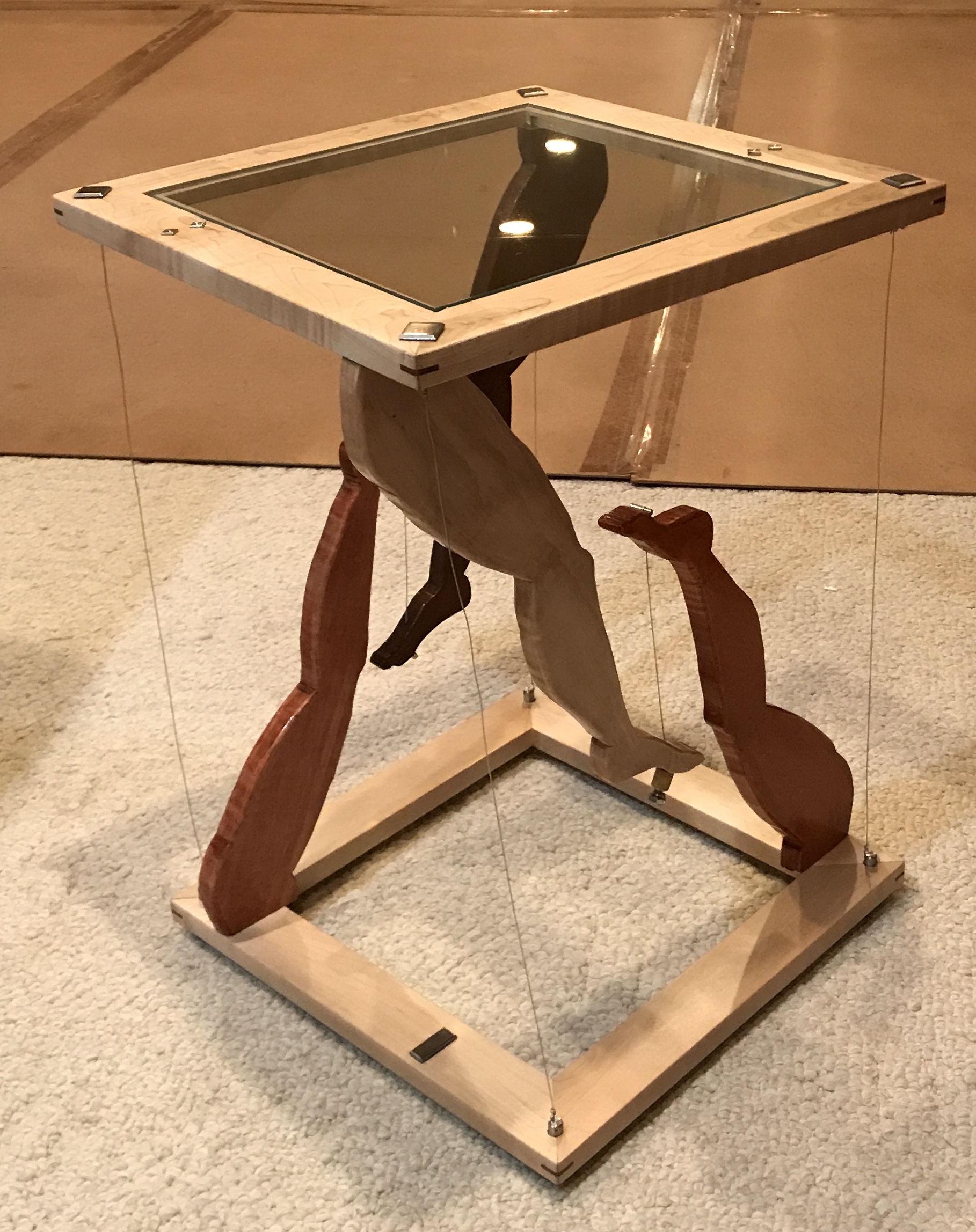
One final attempt was made to right the top. A second adjuster was made for the second set of legs. It was the same design as the first. A brass nut was made from a scrap of 1/2" brass round. It was knurled, drilled and tapped. It was parted off at 1/2". The screw with the drilled hole from above was cut down to 3/4" of threads. Putting it all together still leaves a twist, even though all of the wires are tight, at least as judged by my ear.